
Sprinter 2500 L5-2.7L DSL Turbo (2002)
Connector views show the connector and the circuits involved with that connector. The connectors are identified using the name/number on the diagram
sheets, and a master list can be found at Vehicle/Diagrams.
Connector, Ground and Splice Identification and Location
CAUTION: Not all connectors are serviced. Some connectors are serviced only with a harness. A typical example might be the Supplemental Restraint
System connectors. Always check parts availability before attempting a repair.
Identification
Connectors, grounds, and splices are identified as follows:
-
In-line connectors located in the engine compartment are C100 series numbers
-
In-line connectors located in the Instrument Panel area are C200 series numbers.
-
In-line connectors located in the body are C300 series numbers.
-
Jumper harness connectors are C400 series numbers.
-
Grounds and ground connectors are identified with a "G" and follow the same series numbering as the in-line connectors.
-
Splices are identified with an "S" and follow the same series numbering as the in-line connectors.
-
Component connectors are identified by the component name instead of a number. Multiple connectors on a component use a C1, C2, etc.
identifier.
Locations
Vehicle/Locations contains the master connector/ground/splice location index charts with hyperlinks to the applicable location illustrations. The
illustrations contain the connector name (or number)/ground number/splice number and component identification.
The abbreviation T/O is used in the location column to indicate a point in which the wiring harness branches out to a component. The abbreviation
N/S means Not Shown in the illustrations.
PLEASE NOTE: The master location index charts contain numerous items that may not be applicable to all vehicle models. If a link on the master
location index chart to a figure is not functional, that means that the chart item and/or figure in question does NOT apply to the vehicle model selected.
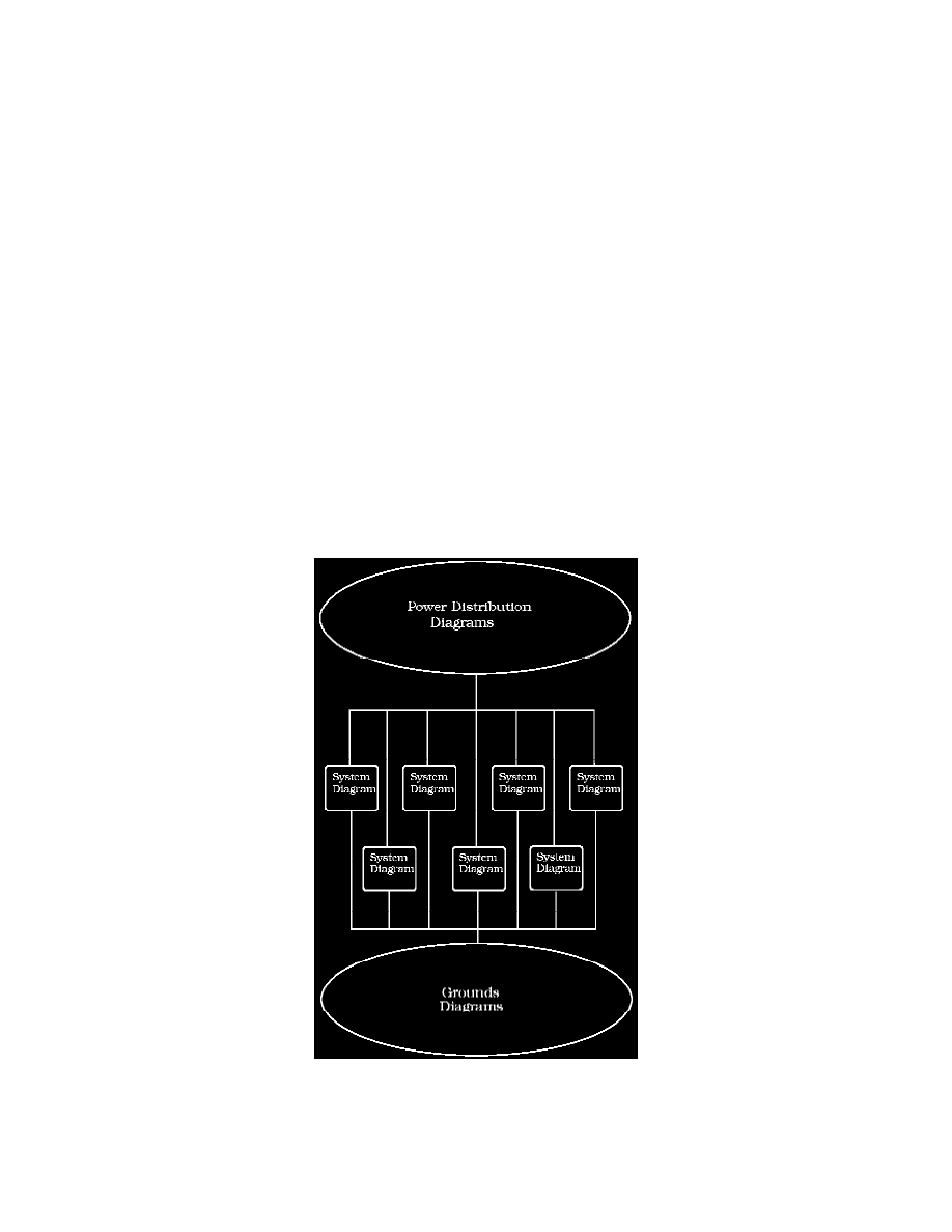
How to Find Wiring Diagrams
Diagrams are presented in three main categories:
^
Power Distribution Diagrams
Circuits feeding/protecting the system diagrams
^
System Diagrams
Component Circuits that work together as a system
^
Grounds Diagrams