
Sprinter 2500 L5-2.7L DSL Turbo (2002)
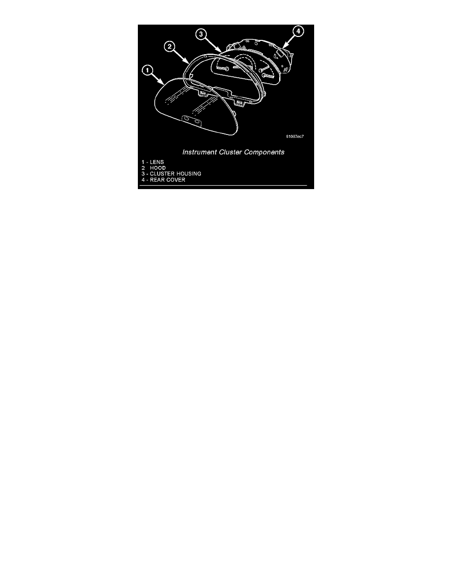
Instrument Cluster Components
The EMIC gauges and indicators are visible through a dedicated opening in the cluster bezel on the instrument panel and are protected by a clear plastic
cluster lens that is secured by eight integral latches to the molded black plastic cluster hood. Four, black plastic multi-function indicator switch push
buttons protrude through dedicated holes in a rectangular black plastic switch bezel that is integral to the cluster lens and located near the lower edge of
the cluster directly below the multifunction indicator LCD unit. The cluster hood serves as a visor and shields the face of the cluster from ambient light
and reflections to reduce glare. The cluster hood has eight integral latches that engage eight integral latch tabs on the cluster rear cover, sandwiching the
cluster housing unit between the hood and the rear cover. The cluster hood also has two integral pivot loops molded into its underside that engage two
pairs of molded pivot hooks that are integral to the top of the instrument panel base structure. These pivots allow the cluster to be rolled rearward to ease
service access to the wire harness connectors at the back of the cluster.
The rear of the cluster housing and the EMIC electronic circuitry are protected by the molded plastic rear cover. A mounting ear at each upper corner of
the rear cover are used to secure the EMIC to the molded plastic instrument panel base unit with two screws. The rear cover includes clearance holes for
the two cluster connector receptacles on the cluster electronic circuit board. The connector receptacles on the back of the cluster electronic circuit board
connect the EMIC to the vehicle electrical system through two take outs with connectors from the vehicle wire harness. The EMIC rear cover includes a
molded mounting tab and a latch feature that secures the RKE/immobilizer module to the back of the cluster. The RKE/immobilizer module is connected
to the vehicle electrical system through a separate take out and connector of the vehicle wire harness.
Located between the rear cover and the cluster hood is the cluster housing. The molded plastic cluster housing serves as the carrier for the cluster
electronic circuit board and circuitry, the cluster connector receptacles, the gauges, a Light Emitting Diode (LED) for each cluster indicator and general
illumination lamp, the multi-function indicator LCD unit, electronic tone generators, the cluster overlay, the gauge pointers, the multi-function indicator
switches and the four switch push buttons.
The cluster overlay is a laminated plastic unit. The dark, visible, outer surface of the overlay is marked with all of the gauge dial faces and graduations,
but this layer is also translucent. The darkness of this outer layer prevents the cluster from appearing cluttered or busy by concealing the cluster
indicators that are not illuminated, while the translucence of this layer allows those indicators and icons that are illuminated to be readily visible. The
underlying layer of the overlay is opaque and allows light from the LED for each of the various indicators and illumination lamps behind it to be visible
through the outer layer of the overlay only through predetermined cutouts. A rectangular opening in the overlay at the base of the speedometer provides a
window through which the illuminated multi-function indicator LCD unit can be viewed.
Several versions of the EMIC module are offered on this model. These versions accommodate all of the variations of optional equipment and regulatory
requirements for the various markets in which the vehicle will be offered. The microprocessor-based EMIC utilizes integrated circuitry, Electrically
Erasable Programmable Read Only Memory (EEPROM) type memory storage, information carried on the Controller Area Network (CAN) data bus,
along with several hard wired analog and multiplexed inputs to monitor systems, sensors and switches throughout the vehicle.
In response to those inputs, the hardware and software of the EMIC allow it to control and integrate many electronic functions and features of the vehicle
through both hard wired outputs and the transmission of electronic message outputs to other electronic modules in the vehicle over the CAN data bus.
Besides typical instrument cluster gauge and indicator support, the electronic functions and features that the EMIC supports or controls include the
following:
-
Active Service System - In vehicles equipped with the Active Service SYSTem (ASSYST) engine oil maintenance indicator option, the EMIC
electronic circuit board includes a second dedicated microprocessor. This second microprocessor evaluates various data including time, mileage,
and driving conditions to calculate the required engine oil service intervals, and provides both visual and audible alerts to the vehicle operator
when certain engine oil maintenance services are required.