
Sprinter 2500 L5-2.7L DSL Turbo (2002)
Engine Control Module: Description and Operation
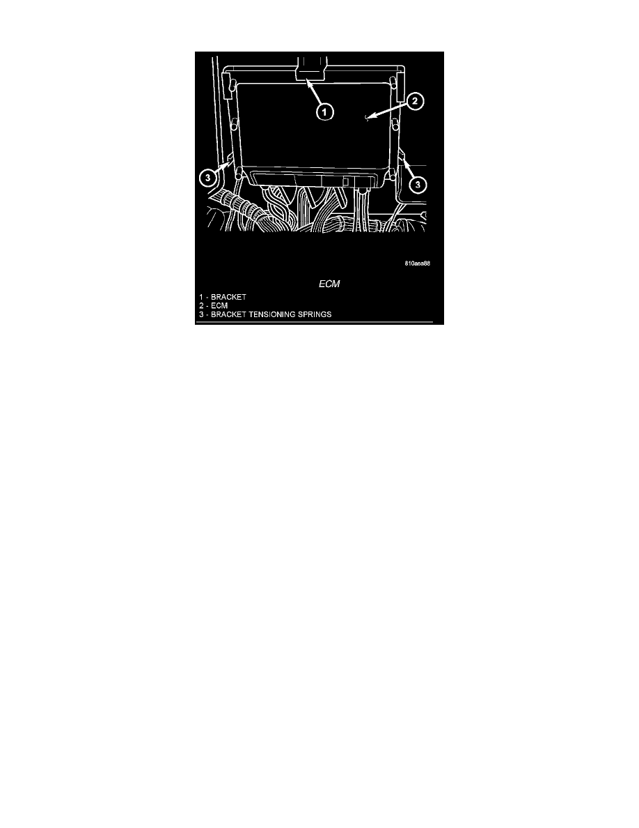
ECM
The electronic control module (ECM) is mounted to the left lower dash panel and consists of an electronic printed circuit board which is designed as a
multi-layer board assembly fitted on both sides. The routing of the five wiring harness connectors at the ECM connectors are split into interfering cables
and sensitive cables in order to achieve improved electromagnetic compatibility. The ECM stores engine specific data, monitors the connected sensor
and analyzes their measurement.
Its task consists in controlling the following systems in line with the analysis of the input signals:
-
Fuel Supply System
-
Injected Quantity Control
-
Emission Control System
-
Charge Pressure Control
-
Cruise Control
-
A/C Compressor Shut-Off
-
Pre-Heating Output Relay for the Glow Plugs
-
Vehicle Theft
-
Air Bag
-
Monitors inputs/outputs, checks plausibility and stores faults
-
Share information with other control modules
-
Diagnosis
If a sensor should fail, provided the fault is not serious, the ECM will continue to operate the engine in Limp-Home Mode (emergency mode) using a
default value for the missing signal. The ECM ensures that continuing to operate the engine will not cause damage or effect safety,otherwise a Engine
shut-off process will be carried out.