
Sprinter 3500 V6-3.0L DSL Turbo (2007)
Body Control Module: Description and Operation
Module-Body Control
Description
DESCRIPTION
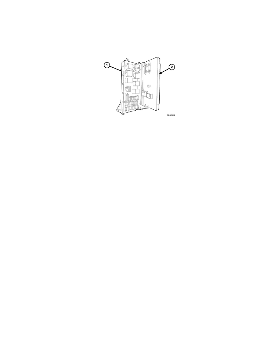
The Body Control Module (BCM) (also known as the Signal Acquisition and Actuation Module/SAM) (2) is located beneath the driver side end of the
instrument panel in the passenger compartment, where it is secured to the fuse and relay block (also known as the SRB) (1). The fuse and relay block is
the interface between the vehicle wire harnesses. The fuse and relay block also contains the fuses and relays used to protect and operate many of the
electrical circuits in the vehicle.
The BCM is enclosed in a molded plastic housing with several integral external connectors that connect it to the vehicle electrical system through take
outs with connectors from the vehicle wire harnesses. The BCM also has an integral interface connector that joins it through a connector receptacle that
is integral to the fuse and relay block housing to the circuitry within the fuse and relay block. This connector is referred to as the BCM - fuse and relay
block connector.
The BCM housing has a horizontal nailhead pin on each side of the interface connector at the top that is engaged into half-round cradle formations on
each side at the top of the fuse and relay box BCM interface connector receptacle. After the two pins are engaged in these cradle formations, the lower
end of the BCM is rotated downward until the interface connector halves are fully engaged, then a screw is inserted through a mounting tab at the bottom
of the BCM - fuse and relay block connector and tightened to secure the connection to the fuse and relay block.
The BCM utilizes integrated circuitry, electronic messages received over the Controller Area Network (CAN) data bus from other electronic modules,
along with many hard wired inputs to monitor numerous sensor and switch inputs throughout the vehicle. In response to those inputs, the internal
circuitry and programming of the BCM allow it to control and integrate many electronic functions and features through both hard wired outputs and the
transmission of electronic message outputs over the CAN data bus to other electronic modules in the vehicle.
The electronic functions and features that the BCM supports or controls include the following:
-
Central Locking - The BCM controls outputs for the central locking/unlocking features on all passenger side front, the driver and passenger
sliding side, and all rear doors.
-
Exterior Lighting Control - The BCM is the master control unit for both the standard and optional exterior lighting systems.
-
Front Power Window System Control - The BCM provides the control for the front passenger side door power window.
-
Headlamp Cleaning System Control - The BCM controls the output to the optional headlamp cleaning system.
-
Heated Rear Glass System Control - The BCM controls the output to the optional electrically heated rear door glass.
-
Heated Windshield Glass System Control - The BCM controls the output to the optional electrically heated windshield glass.
-
Horn Control - The BCM controls the outputs to the horn.
-
Interior Lighting Control - The BCM controls the outputs for the standard and optional interior and instrument panel control lighting systems.
-
Rear Power Window System Control - The BCM provides the control for the optional rear power vent windows on both the driver and
passenger side.
-
Remote Keyless Entry System Control - The BCM provides the Remote Keyless Entry (RKE) system features.
-
Wiper and Washer System Control - The BCM provides controls for the standard front and the optional rear wiper and washer systems.
-
Vehicle Theft Security System Control - The BCM provides control of the optional Vehicle Theft Security System (VTSS) features.
Several versions of the BCM are available, which vary depending upon the standard and optional vehicle equipment. The size of the BCM housing
changes with each version, which should aid in identification. Be certain that a new BCM is the correct replacement for one that is being removed.
The BCM has programmable memory that can be reprogrammed using a diagnostic scan tool and Flash reprogramming procedures; otherwise, the BCM
cannot be adjusted or repaired. If ineffective or damaged the entire BCM unit must be replaced.
Operation