
Sprinter 3500 V6-3.0L DSL Turbo (2007)
IDENTIFICATION
In-line connectors are identified by a number, as follows:
-
In-line connectors located in the engine compartment are C100 series numbers
-
In-line connectors located in the Instrument Panel area are C200 series numbers.
-
In-line connectors located in the body are C300 series numbers.
-
Jumper harness connectors are C400 series numbers.
-
Grounds and ground connectors are identified with a "G" and follow the same series numbering as the in-line connectors.
-
Splices are identified with an "S" and follow the same series numbering as the in-line connectors.
-
Component connectors are identified by the component name instead of a number. Multiple connectors on a component use a C1, C2, etc.
identifier.
LOCATIONS
Connector, Ground and Splice Locations contains connector/ground/splice location illustrations. The illustrations contain the connector name (or
number)/ground number/splice number and component identification. Connector/ground/splice location charts in Connector, Ground and Splice
Locations reference the figure numbers of the illustrations.
The abbreviation T/O is used in the component location section to indicate a point in which the wiring harness branches out to a component. The
abbreviation N/S means Not Shown in the illustrations
Removal
REMOVAL
1. Disconnect battery.
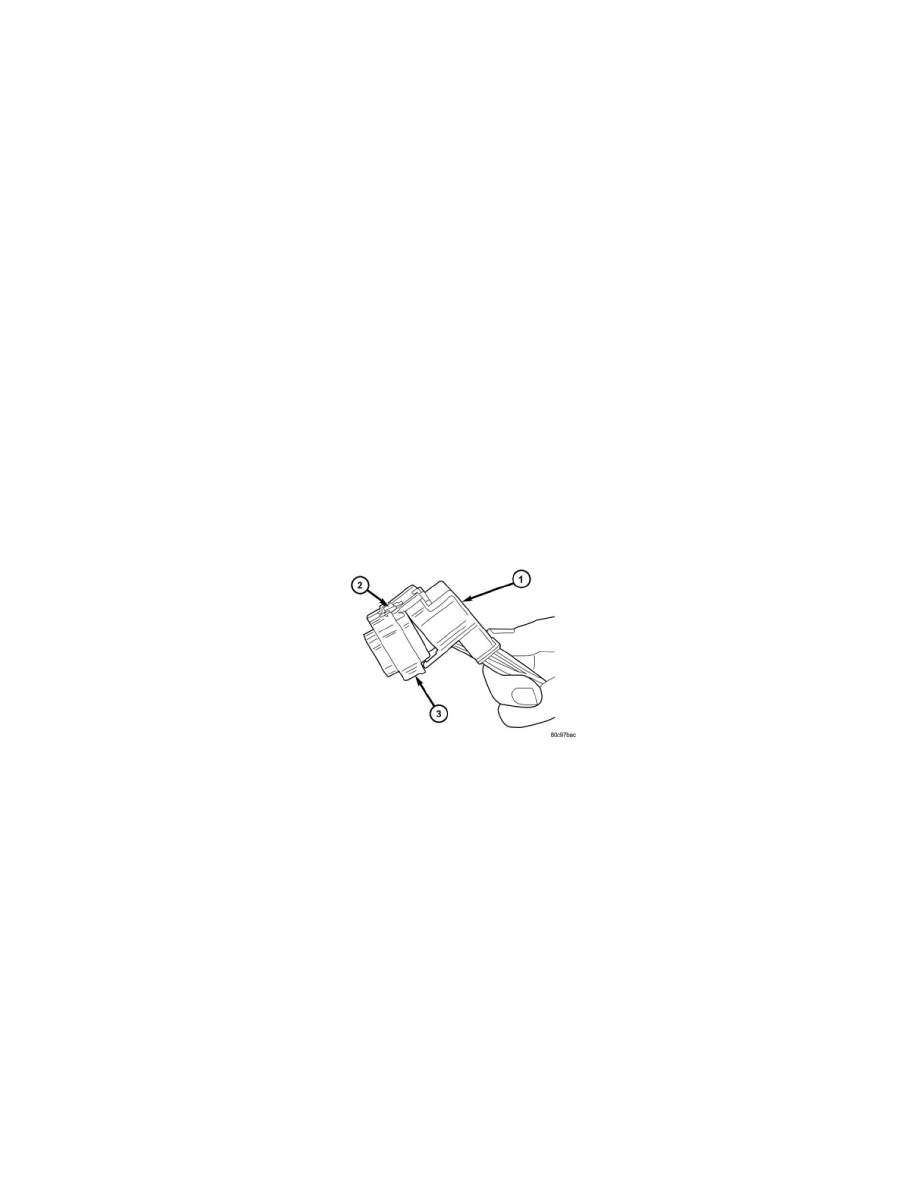
2. Release Connector Lock.
3. Disconnect the connector being repaired from its mating half/component.
4. Remove the dress cover (if applicable).
5. Release the Secondary Terminal Lock, if required.
6. Position the connector locking finger away from the terminal using the proper special tool. Pull on the wire to remove the terminal from the
connector.
Installation
INSTALLATION
1. Insert the removed terminal in the same cavity on the repair connector.
2. Repeat steps for each terminal in the connector, being sure that all wires are inserted into the proper cavities. For additional connector pin-out
identification, refer to the wiring diagrams.
3. When the connector is re-assembled, the secondary terminal lock must be placed in the locked position to prevent terminal push out.
4. Replace dress cover (if applicable).
5. Connect connector to its mating half/component.
6. Connect battery and test all affected systems.
Removal
REMOVAL
1. Disconnect the battery.
2. Locate the diode in the harness, and remove the protective covering.
3. Remove the diode from the harness, pay attention to the current flow direction.