
Metro L3-61 1.0L (1990)
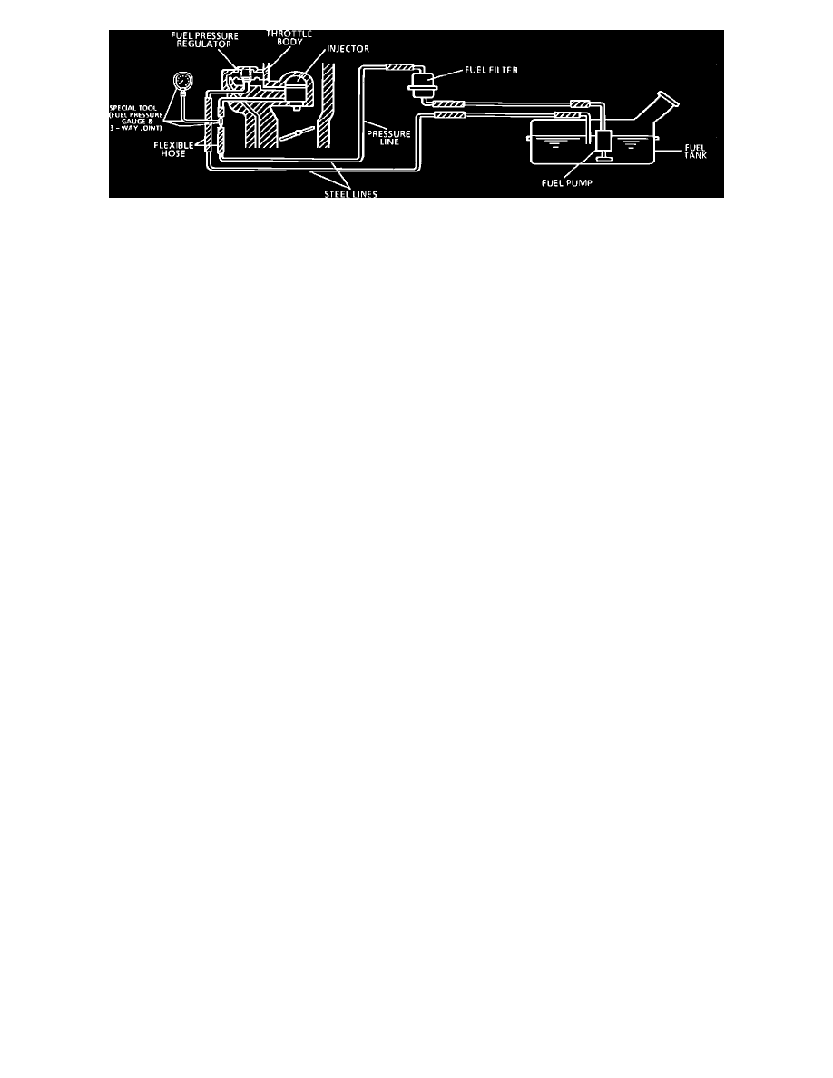
Chart A-7 Fuel System Diagram
CIRCUIT DESCRIPTION:
When the ignition switch is turned "ON," the electronic control module (ECM) will turn "ON" the in-tank fuel pump. It will remain "ON" as long as the
engine is cranking or running, and the ECM is receiving reference pulses. If there are no reference pulses, the ECM will shut "OFF" the fuel pump in
about 2 seconds after ignition "ON" or engine stops. The pump will deliver fuel to the fuel rail and injectors, then to the pressure regulator, where the
system pressure is controlled to about 160-210 kPa (23.2-30.5 psi) depending on engine operating conditions. Excess fuel is then returned to the fuel
tank.
TEST DESCRIPTION: Numbers below refer to circled numbers on the diagnostic chart.
1.
Wrap a shop towel around the fuel pressure connector to absorb any small amount of fuel leakage that may occur when installing the gauge.
Ignition "ON" pump pressure should be 160-210 kPa (23.2-30.5 psi). This pressure is controlled by spring pressure within the regulator assembly.
2.
When the engine is idling, the manifold pressure is low (high vacuum) and is applied to the fuel regulator diaphragm. This will offset the spring
and result in a lower fuel pressure. This idle pressure will vary somewhat depending on barometric pressure, however, the pressure idling should
be less indicating pressure regulator control.
3.
Pressure that continues to fail quickly is caused by one of the following:
^
In-tank fuel pump check valve not holding.
^
Pump coupling hose.
^
Fuel pressure regulator valve leaking.
^
Injector(s) sticking open.
4.
An injector sticking open can best be determined by checking for a fouled or saturated spark plug(s).
^
Pressurize the fuel system and observe for injector leaking.
CAUTION: Be sure injector is not allowed to spray on engine. This should be carefully followed to prevent fuel spray on engine which would
cause a fire hazard.
NOTE: The fuel system contains the following components: an ECM controlled relay, a fuel pump, and a throttle body with a pressure regulator. Care
should be taken when servicing this system due to the high presure in the fuel lines.
CAUTION: This test is used to check the components for proper operation. When servicing the fuel system all procedures should be followed and care
should be exercised to prevent personal injury or damage to the vehicles components. All procedures should be read through carefully and a through
understanding of the procedure before performing the test procedures.
FUEL PRESSURE RELIEF PROCEDURE:
CAUTION: To reduce the risk of fire and personal injury, it is necessary to relieve the fuel system pressure before servicing the fuel system. After
relieving system pressure, a small amount of fuel may be released when servicing fuel lines or connections. In order to reduce the chance of personal
injury, cover fuel line fittings with a shop towel before disconnecting, to catch any fuel that may leak out. Place the towel in an approved container when
disconnect is completed.
FUEL PRESSURE GAUGE INSTALLATION:
1.
Loosen fuel filler cap to relieve tank vapor pressure.
2.
Place transaxle gear shift lever in Neutral for M/T models, or Park for A/T models. Set parking brake and block drive wheels.
3.
Remove main fuse block cover and engine coolant reservoir from its bracket.