
Metro L3-61 1.0L (1990)
Data Link Connector: Description and Operation
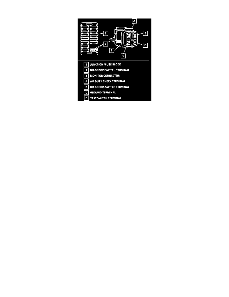
Diagnosis And Test Switch Terminals
There are two diagnosis switch terminals; one included in the junction/fuse block and the other in the monitor connector in the engine compartment.
When either diagnosis switch terminal is grounded, a diagnosis signal is fed to the ECM which then outputs a self-diagnosis code and at the same time
fixes the "ON" time of the ISC solenoid valve.
The test switch terminal is included in the monitor connector. When this terminal is grounded, the ECM sets the ignition timing to base timing. When
both test switch terminal and diagnosis switch terminal are not grounded, ECM outputs A/F duty cycle through the A/F duty cycle check terminal.