
Metro L3-61 1.0L (1990)
Throttle Position Sensor: Adjustments
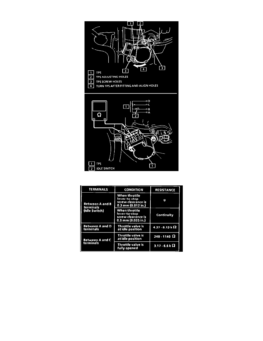
TPS Check
TPS Output Check
1.
Connect DVM to terminals "A" and "B."
2.
Turn TPS fully counterclockwise, then clockwise until DVM reads zero (no continuity).
3.
Check continuity between terminals "A" and "B" with a 0.9 mm (0.035") feeler gauge inserted between throttle lever stop screw and throttle lever.
DVM should read zero.
4.
Repeat step above with a 0.3 mm (0.012") feeler gauge. The DVM should read continuity.
5.
Tighten retaining screws. Refer to SPECIFICATIONS.
6.
Connect TPS electrical connector.