
Metro L4-079 1.3L VIN 9 TBI (1995)
Description
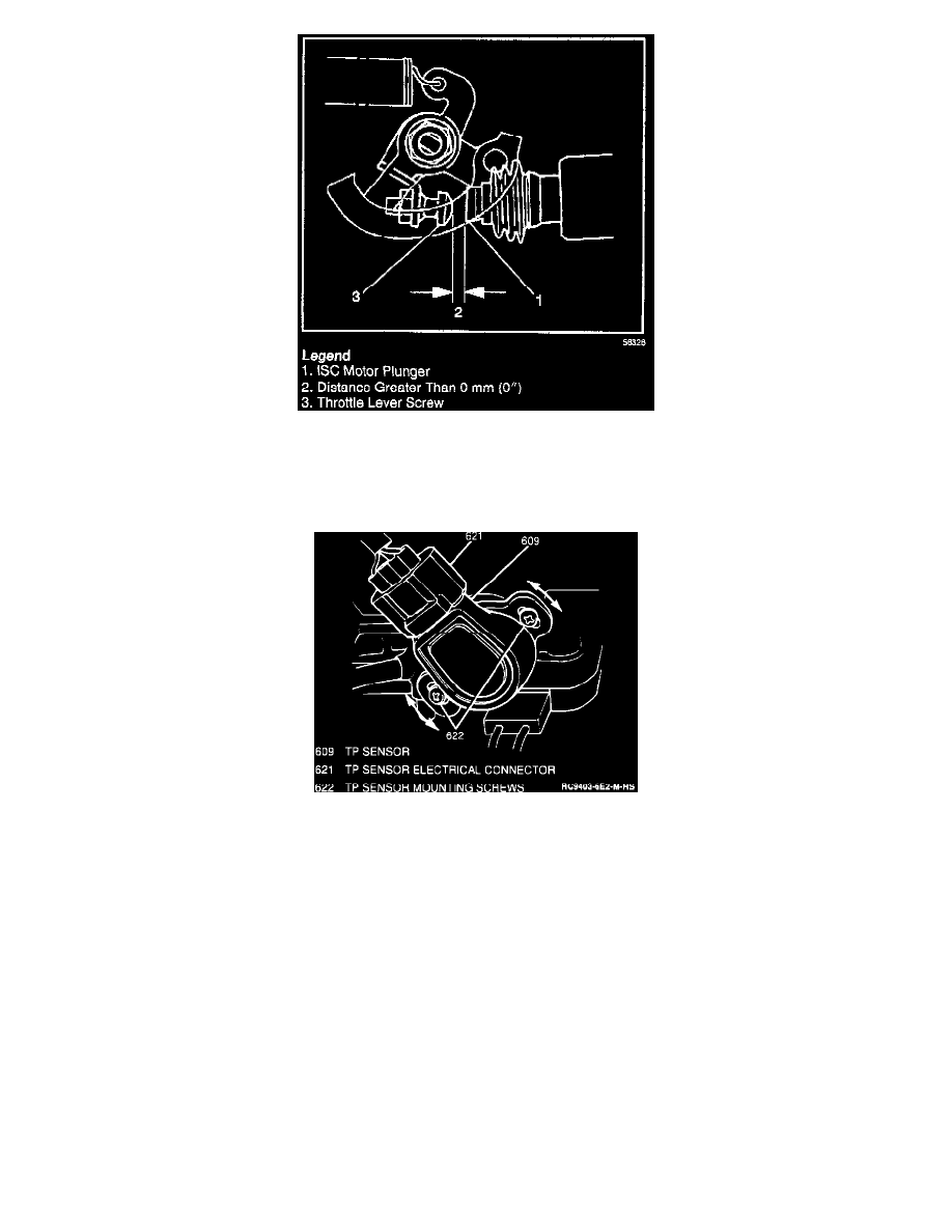
B. Inspect the Idle Speed Control (ISC) motor plunger. If ISC motor plunger is contacting throttle lever screw, then the engine must he brought to
operating temperature (refer to image).
C. Connect a Tech 1 to the Data Link Connector (DLC) and turn the ignition switch to "ON."
TPS Adjustment Metro W/ Upgraded Emissions
D. While observing TP sensor voltage on the Tech 1 scan tool, turn the TP sensor until the voltage reading is 0.98 to 1.02 volts (refer to image).
Tighten the TP sensor screws to 2.0 Nm (18 lb in).