
Metro L4-079 1.3L VIN 9 TBI (1995)
Throttle Position Sensor: Service and Repair
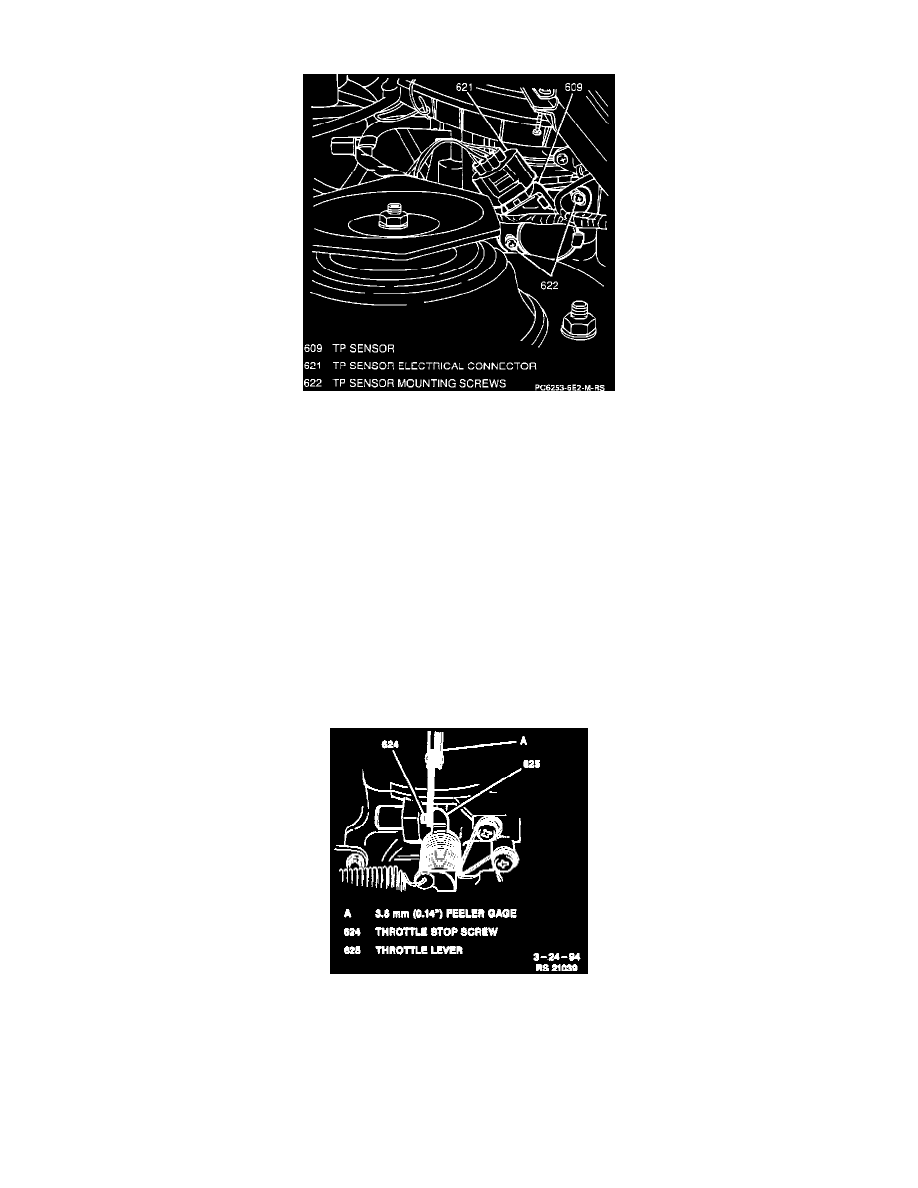
Throttle Position (TP) Sensor
THROTTLE POSITION SENSOR REPLACEMENT
REMOVE OR DISCONNECT
1. Negative (-) battery cable.
2. One bolt, one nut, PCV hose, Intake Air Temperature (IAT) sensor electrical connector and Air Cleaner (ACL) from Throttle Body Fuel Injection
(TBI) unit.
3. Throttle Position (TP) sensor electrical connector.
4. Two screws and TP sensor from TBI unit.
INSTALL OR CONNECT
1. TP sensor to TBI unit; secure with two screws. Do not tighten fully.
2. TP sensor electrical connector.
3. PCV hose, IAT electrical connector and ACL to TBI; secure with one bolt and one nut. Tighten ACL bolt to 15 Nm (11 lb ft).
4. Negative (-) battery cable. Tighten negative (-) battery cable-to-negative (-) battery terminal retainer to 15 Nm (11 lb ft).
TP SENSOR ADJUSTMENT
Inserting Feeler Gauge
A. Insert a 3.5 mm (0.14 inch) feeler gage between throttle stop screw and throttle lever (refer to image).