
Prizm L4-108 1.8L DOHC VIN 8 MFI (1995)
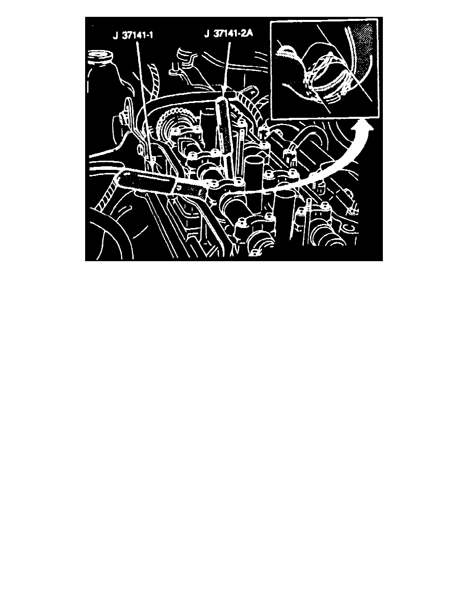
Fig. 6 Valve Spring Depression
Measure and adjust valve clearance while the engine is cold.
1. Disconnect battery ground cable.
2. Remove cylinder head cover.
3. Set No. 1 cylinder at TDC on the compression stroke.
4. Turn crankshaft to align groove in crankshaft pulley with "0" mark on No. 1 timing belt cover. Ensure valve lifters on No. 1 cylinder have
freeplay. If not, rotate crankshaft pulley 360° and align the "0" mark on timing belt cover.
5. Measure and record valve lash clearance between the cam lobe and the adjusting shim on cylinders shown in Fig. 4 .
6. Rotate crankshaft 360° and align groove with "0" mark timing belt cover.
7. Measure and record valve lash clearance between the cam lobe and the adjusting shim on cylinders shown in Fig. 5 .
8. If clearance is not within specifications, obtain the valve clearance adjustment set tool No. J-37141-A, or equivalent.
9. Insert valve spring compression Tool No. J-37141-1, or equivalent, between the camshaft and lifter adjusting shim. This action will compress the
valve spring and push lifter down.
10. Insert lifter holding tool No. J-37141-2A, or equivalent, between camshaft and lifter. Position bottom edge of tool on lifter and not on adjusting
shim. The lifter appears to be a sleeve around the adjusting shim. This action will hold the lifter away from camshaft, Fig. 6 .
11. Remove spring compression tool No. J-37141-1, or equivalent. Lifter holding tool No. J-37141-2A should hold lifter down away from camshaft.
12. Remove adjusting shim with a small screwdriver and magnetic finger, Fig. 7 .