
Prizm L4-108 1.8L DOHC VIN 8 MFI (1995)
Fuel Injector Installation
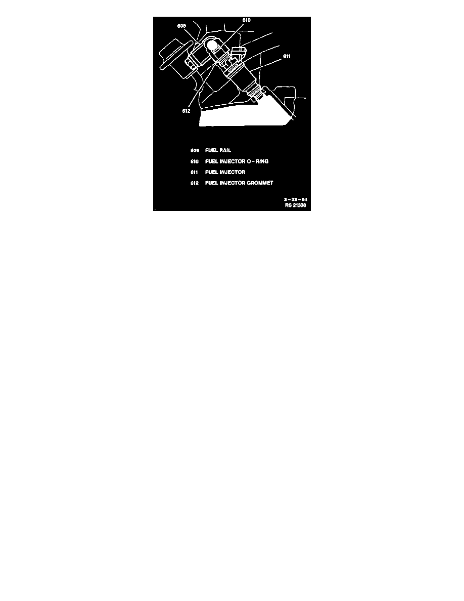
3. Four injectors to the fuel rail; positioning injector connector upward.
4. Four new insulators and two spacers in position on the intake manifold.
5. Fuel injectors with fuel rail to intake manifold; secure with two bolts. Do not tighten fully.
NOTE: Check that the fuel injectors rotate smoothly. If the injectors do not rotate smoothly, the probable cause is Incorrect installation of the
O-rings. Replace the O-rings if necessary and position the injector connector upward.
^
Tighten fuel rail-to-intake manifold bolts to 15 Nm (11 lb. ft.).
6. Fuel feed inlet hose to fuel rail; secure with one bolt. Tighten fuel feed hose bolt to 29 Nm (22 lb. ft.).
7. Fuel return hose to fuel pressure regulator; secure with one clamp.
8. Fuel injector electrical connectors.
9. Air intake chamber cover to air intake chamber; secure with two nuts and three Allen-head screws. Tighten air intake chamber cover nuts and
Allen head screws to 19 Nm (14 lb. ft.).
10. One vacuum hose to fuel pressure regulator.
11. PCV hose to PCV valve; secure with one clamp.
12. PCV hose to air intake chamber; secure with one clamp.
13. EGR valve and pipe with two new gaskets; secure with four nuts (If equipped). Tighten EGR valve and pipe nuts to 13 Nm (115 lb. in.).
14. EGR gas temperature sensor electrical connector (If equipped).
15. Engine hanger assembly with EGR vacuum modulator (If equipped); secure with one nut and bolt. Tighten engine hanger assembly nut and bolt to
28 Nm (21 lb. ft.).
16. EGR hoses to EGR valve and pipe (If equipped).
17. Fuel feed/return pipe/hose bracket to intake manifold; secure with two bolts. Tighten fuel feed/return pipe/hose bracket bolts to 10 Nm (89 lb. in.).
18. New gasket to intake manifold.
19. Throttle body; secure with two nuts and two bolts. Tighten throttle body nuts and bolts to 22 Nm (16 lb. ft.).
20. IAC valve electrical connector.
21. TP sensor electrical connector.
22. One EVAP vacuum hose to throttle body.
23. Two EGR vacuum hoses to throttle body (If equipped).
24. TV cable to cable bracket and throttle lever; secure with two nuts (automatic transaxle only). Do not tighten fully. Adjust TV cable. Refer to
Transmission and Drivetrain / Automatic Transmission/Transaxle.
25. Accelerator cable to cable bracket and throttle lever; secure with two nuts. Tighten accelerator cable adjusting nuts to 8 Nm (71 lb. in.).
26. ACL hose and cap to throttle body.
27. Four cap clips to ACL. Tighten ACL hose clamp bolt to 15 Nm (11 lb. ft.).
28. IAT sensor electrical connector.
29. Accelerator cable and cruise control cable (If equipped) to ACL assembly clip.
^
Refill engine coolant.
30. Negative (-) battery cable. Tighten negative (-) battery cable-to-negative (-) battery terminal retainer to 15 Nm (11 lb. ft.).
AFTER REPAIR INSPECTION
Turn ignition switch to "ON" and momentarily connect a jumper between Data Link Connector (DLC) terminals "+B" and "FP" to pressurize the