
Prizm L4-108 1.8L DOHC VIN 8 MFI (1995)
^
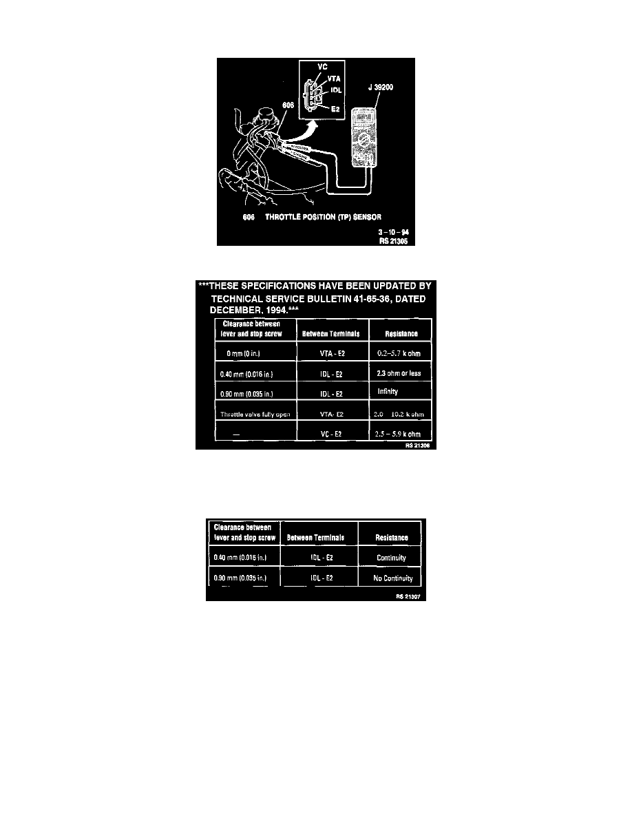
Insert a feeler gage between the throttle stop screw and the throttle lever. On vehicles equipped with throttle opener, disconnect the throttle opener
vacuum hose from the throttle body and apply vacuum to it.
Measuring TP Sensor Resistance
Throttle Position Sensor Resistance Specifications
^
Using a DVOM, check for resistance between the terminals of the TP sensor according to the Resistance Specification Chart.
^
Rotate the TP sensor if necessary to adjust. Tighten TP sensor attaching screws.
Throttle Position Sensor Continuity Chart
CONTINUITY CHECK
Recheck TP sensor continuity according to the Throttle Position Continuity Chart.
INSTALL OR CONNECT
^
TP sensor electrical connector and throttle opener vacuum hose to throttle body on vehicles equipped with throttle opener.
^
Negative (-) battery cable. Tighten negative battery cable-to-negative (-) battery terminal retainer to 15 Nm (11 lb. ft.).
NOTICE: If vehicle is equipped with a throttle opener, refer to Fuel Delivery and Air Induction / Throttle Positioner for throttle opener
adjustment procedure.