
Prizm L4-108 1.8L DOHC VIN 8 MFI (1995)
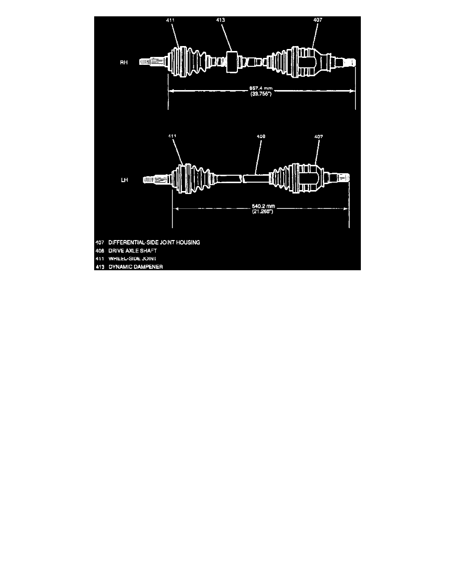
Fig. 14 Axle Length.
DISASSEMBLE
NOTE: Place match marks on all components before removal from shaft.
1. Secure axle assembly in a soft-jawed vise.
2. Remove boot retaining clamps, Fig. 13 .
3. Remove boot from outer housing, then outer housing from shaft.
4. Remove tripot retaining ring using snap ring pliers.
5. Remove tripot from shaft.
6. Remove boot from shaft.
ASSEMBLE
1. Apply GM grease part No. 7845393, or equivalent, to tripot housing and spider joint.
2. Install boot clamp on drive axle shaft Fig. 13 , then the boot. Do not tighten clamp at this time.
3. Install spider joint assembly on drive axle using a brass drift and hammer, then the snap ring.
4. Install outer housing onto spider assembly.
5. Install axle shaft snap ring into outer housing.
6. Connect boot and boot clamp to tripot outer housing.
7. Refer to Fig. 14 , for axle length specifications when installing and tightening boot clamps.
8. Ensure boot is not stretched, collapsed, twisted or kinked when installing boot bands.
Outer Joint