
Prizm L4-1600cc 1.6L DOHC VIN 5 (1989)
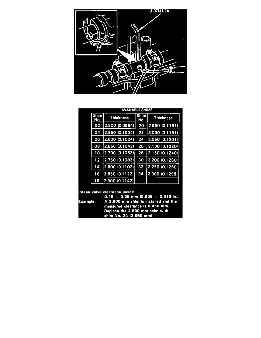
Fig. 19 Removing Adjusting Shim. 16 Valve Engine
Fig. 20 Valve Shim Size Chart. 16 Valve Engine
16 VALVE ENGINE
Measure and adjust valve clearance while the engine is cold.
1.
Disconnect battery ground cable.
2.
Remove cylinder head cover.
3.
Set No. 1 cylinder at TDC on the compression stroke.
4.
Turn crankshaft to align groove in crankshaft pulley with ``0'' mark on No. 1 timing belt cover.
Ensure that valve lifters on No. 1 cylinder have
freeplay. If not, rotate crankshaft pulley 360° and align the ``0'' mark on timing belt cover.
5.
Measure and record valve lash clearance between the cam lobe and the adjusting shim on cylinders shown in
Fig. 16.
6.
Rotate crankshaft 360° and align groove with ``0'' mark timing belt cover.
7.
Measure and record valve lash clearance between the cam lobe and the adjusting shim on cylinders shown in
Fig. 17.
8.
If clearance is not within specifications, obtain the valve clearance adjustment tool set No. J-37141-A, or equivalent.
9.
Insert valve spring compression tool No. J-37141-1, or equivalent, between the camshaft and lifter adjusting shim. This action will compress the
valve spring and push lifter down.
10.
Insert lifter holding tool No. J-37141-2A, or equivalent, between camshaft and lifter. Position bottom edge of tool on lifter and not on adjusting
shim. The lifter appears to be a sleeve around the adjusting shim. This action will hold the lifter away from camshaft,
Fig. 18.
11.
Remove spring compression tool No. J-37141-1. Lifter holding tool No. J-37141-2A should hold lifter down away from camshaft.
12.
Remove adjusting shim with a small screwdriver and magnetic finger,
Fig. 19.