
Prizm L4-1600cc 1.6L DOHC VIN 5 (1989)
Band Apply Servo: Service and Repair
Removal
1.
Disconnect negative battery cable.
2.
Raise and support vehicle, then drain fluid from transaxle.
3.
Remove shift cable bracket at transaxle.
4.
Install second brake servo compressor tool No. J-35549-A or equivalent and compress second brake servo.
5.
Remove second brake servo snap ring and second brake servo compressor.
6.
Remove cover.
7.
Remove piston, then the outer spring.
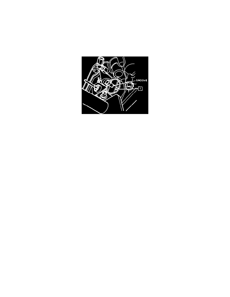
Fig. 7 Second Brake Servo Plunger Installation
Installation
1.
Insert piston, less outer spring, then install snap ring.
2.
Install brake apply rod tool No. J-35679, then observe groove on plunger of tool.
3.
Push button on tool, Fig. 7. This allows tool to push brake apply rod into case. If groove is visible, piston stroke is correct (.059-.118 inch). If
stroke is greater than specified, replace piston rod with 2.870 inch or 2.811 inch rod as needed.
4.
Remove snap ring, then install piston and outer spring.
5.
Install spring compressor tool No. J-35549 to compress spring, then insert snap ring.
6.
Install cover, then the shift cable bracket.
7.
Lower vehicle.