
Prizm L4-1600cc 1.6L DOHC VIN 6 (1990)
5.
Position adjusting bolt guide nut tool No. J-37150 or equivalent over adjusting bolt, tighten tool, then remove snap ring from caliper bore and pull
out adjusting bolt and components.
6.
Remove parking brake strut and cable support bracket, then the parking brake crank torsion spring.
7.
Remove parking brake crank, then the crank boot by tapping on metal portion of boot with screwdriver or similar tool. Do not remove crank boot
unless boot is damaged or excessively worn.
8.
Using a suitable punch, drive stopper pin from caliper.
9.
Inspect all components for damage, wear or corrosion, and replace as necessary.
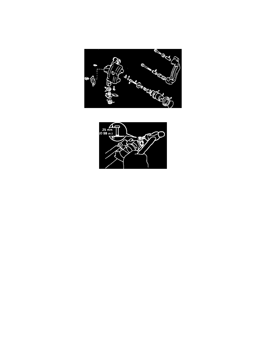
Fig. 7 Lubrication Points For Rear Caliper Assembly
Fig. 8 Installing Stopper Pin
ASSEMBLY
1.
Clean all parts not included in repair kit and dry with compressed air.
2.
Lubricate all components indicated in Fig. 7 with lithium based grease.
3.
Install stopper pin into caliper until pin protrudes .98 inch outward as shown in Fig. 8.
4.
If removed during disassembly, tap parking brake crank boot into position in caliper using a 24mm socket.
5.
Install parking brake crank. Ensure crank boot aligns with groove of crank seal.
6.
Install cable support bracket, then press surface of bracket flush against caliper and torque bolt to 34 ft. lbs. When properly installed, clearance
between parking brake crank and support bracket should be .236 inch.
7.
Install torsion spring, then check that parking brake crank subassembly touches stopper pin.
8.
Install parking brake strut. Before adjusting strut, ensure needle bearing rollers do not catch on caliper bore.
9.
Position new O-ring onto adjusting bolt, then assemble stopper, plate, spring and spring retainer onto bolt. Hand tighten assembly using adjusting
bolt guide nut tool No. J-37150 or equivalent. When properly assembled, inscribed surface of stopper should face upward and notches of spring
retainer should align with notches of stopper.
10.
Position adjusting bolt subassembly into caliper, then install snap ring, ensuring opening faces toward bleeder side of caliper. Pull upward on
adjusting bolt and ensure bolt does not move.
11.
Check operation of parking brake by moving crank by hand. Adjusting bolt should move smoothly, with no evidence of binding.
12.
Install piston seal into caliper bore, then using brake piston driver tool No. J-37149 or equivalent, install piston and bottom in bore by turning tool
clockwise.
13.
Align center of piston stopper groove with protrusion of caliper bore.
14.
Install boot and set ring into caliper.
15.
Using a 21mm socket and suitable vise, press new main pin boot into caliper housing.
16.
Install sliding bushing and bolt, then install caliper as outlined previously.