
Prizm L4-1800cc 1.8L DOHC (1993)
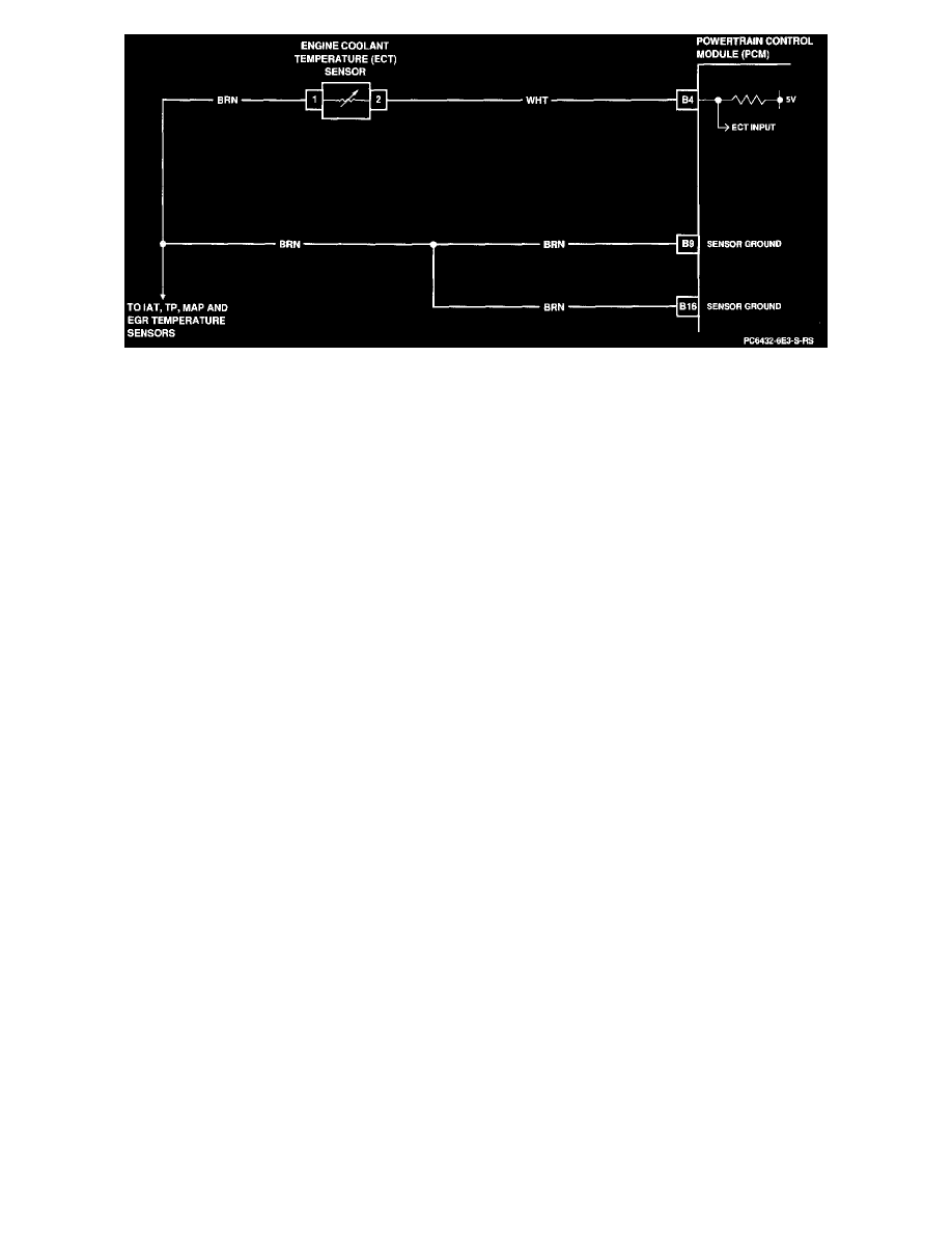
Engine Coolant Temperature Circuit
Failure Modes
DTC 22 will set if either of the following conditions are met for at least 0.5 seconds:
(1) Voltage input at the PCM indicates a very low ECT.
(2) Voltage input at the PCM indicates a very high ECT.
Test Description:
Numbers below refer to circled numbers on the diagnostic chart.
1. This checks for an open or short to ground in the WHT wire between the PCM and ECT sensor and for a faulty ECM.
2. This checks for an open in the BRN wire between the PCM and the ECT sensor and for a faulty PCM.
3. This determines if the problem is a faulty ECT sensor or PCM.
Diagnostic Aids:
Verify that the engine is not overheating and has not been subjected to conditions which could create an overheating condition (ie., overload,
trailer towing, hilly terrain, heavy stop and go traffic, etc.).
A "shifted" (mis-scaled) sensor could result in poor driveability complaints. Measure the resistance of the ECT sensor according to the diagnostic
aids chart on the diagnostic chart. If DTCs 24, 31 and 41 are also set, problem is in sensor ground circuit.
An intermittent may be caused by a poor connection, rubbed through wire insulation, or a wire broken inside the insulation. Inspect hamess
connectors for backed out terminals, improper mating, broken locks, improperly formed or damaged terminals and poor terminal-to-wire
connections before component replacement.