
Prizm L4-1800cc 1.8L DOHC (1993)
Alignment: Description and Operation
Front Wheel Alignment
Fig. 1 Suspension Geometry
Wheel alignment is the angular relationship between the wheels, suspension attaching parts and ground. The angle of the knuckle away from the
vertical, pointing in or out of wheels, tilt of the wheels from vertical (when viewed from front of vehicle) and tilt of suspension members from vertical
(when viewed from side of vehicle), all of these are involved in proper alignment, Fig. 1.
CASTER
Caster is tilting of the front steering axis either forward or backward from the vertical (when viewed from side of vehicle). A backward tilt is positive
(+) and a forward tilt is negative (-). On short and long arm type suspensions you cannot see a caster angle without using a special instrument, but if you
look straight down from the top of the upper control arm to the ground you would find that ball joints do not line up (fore and aft) when a caster angle
other than 0° is present.
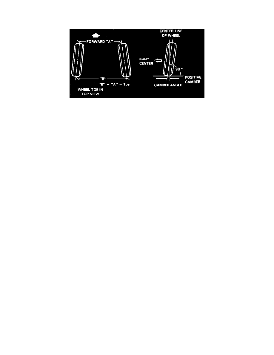
CAMBER
Camber is the tilting of front and rear wheels from the vertical when viewed from front of vehicle. When wheels tilt outward at top, camber is positive
(+). When wheels tilt inward, camber is negative (MI). Amount of tilt is measured in degrees from the vertical and this is camber angle.
TOE
Toe is the turning in or out of wheels. The purpose of toe is to ensure parallel rolling of wheels. Excessive toe-in or toe-out may increase tire wear.
Toe also serves to offset small deflections of the suspension which occurs when vehicle is moving.