
Prizm L4-1800cc 1.8L DOHC (1993)
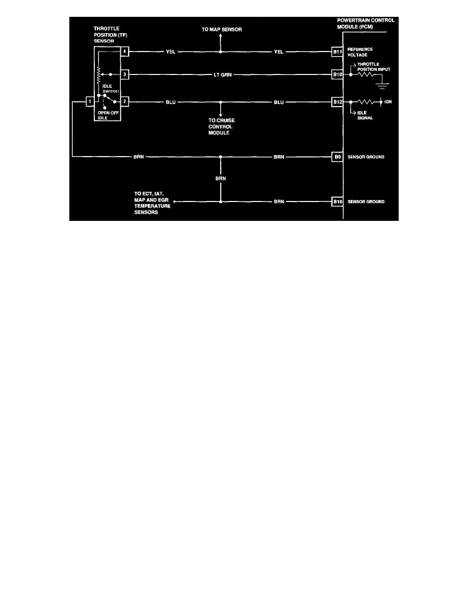
TPS Circuit
Component Failure Mode
By monitoring the "ON/OFF" signal and sensor output voltage, the PCM detects the throttle valve opening. DTC 41 will set if either of the
following conditions are met for at least 0.5 seconds:
(1) Throttle position input at the PCM indicates wide open throttle when the engine is idling.
(2) Throttle position input at the PCM indicates an idle signal when the engine is off idle.
Test Description:
Numbers below refer to circled numbers on the diagnostic chart.
1. This checks for a fault in the YEL wire between the PCM and TP sensor.
2. This checks for an open in the BRN wire between the PCM and TP sensor.
3. This checks for a fault in the LT GRN wire between the PCM and TP sensor, a faulty PCM or for a misadjusted or faulty TP sensor.
Diagnostic Aids:
Refer to TP sensor adjustment procedures before replacing TP sensor. If DTCs 22, 24 and 31 are also set, problem is in sensor ground circuit.
An intermittent may be caused by a poor connection, rubbed through wire insulation, or a wire broken inside the insulation. Inspect hamess
connectors for backed out terminals, improper mating, broken locks, improperly formed or damaged terminals and poor terminal-to-wire
connections before component replacement.