
Spectrum L4-91.5 1.5L (1989)
Valve Clearance: Adjustments
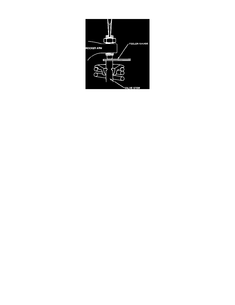
Fig. 6 Adjusting Valve Clearance
1.
Turn crankshaft in normal direction of rotation until No. 1 piston is at TDC of compression stroke.
2.
Measure valve clearance between rocker arm and valve stem, Fig. 6, for No. 1 cylinder intake and exhaust valves, No. 2 cylinder intake valve and
No. 3 cylinder exhaust valve. Adjust valve clearance as necessary to specification listed under SPECIFICATIONS/VALVE CLEARANCE
SPECIFICATIONS.
3.
Rotate crankshaft one complete turn to bring No. 4 cylinder to TDC. Measure valve clearance for No. 2 cylinder exhaust valve, No. 3 cylinder
intake valve and No. 4 intake and exhaust valves. Adjust clearances as necessary.