
Storm L4-1600cc 1.6L DOHC (1991)
MAP Sensor Circuit
CIRCUIT DESCRIPTION:
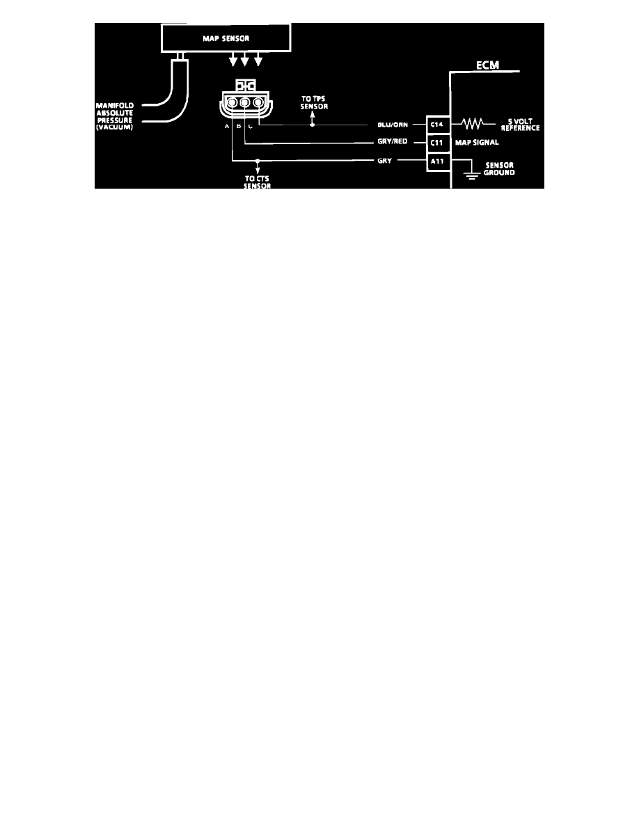
The Manifold Absolute Pressure (MAP) sensor measures manifold pressure (vacuum) and sends that signal to the ECM. The MAP sensor is mainly used
to calculate engine load, which is a fundamental input for spark and fuel calculations. The MAP sensor is also used to determine barometric pressure.
TEST DESCRIPTION: Numbers below refer to circled numbers on the diagnostic chart.
1.
Checks MAP sensor output voltage to the ECM. With the ignition "ON" and the engine stopped, the manifold pressure is equal to atmospheric
pressure and the signal voltage will be high. This voltage, without engine running, represents a barometer reading to the ECM. Comparison of this
BARO reading with a known good vehicle with the same sensor is a good way to check accuracy of a suspect sensor. Readings should be the same
+/- .4 volt.
2.
Applying 34 kPa (10 inches Hg) vacuum to the MAP sensor should cause the voltage to be 1.2-2.3 volts less than the voltage at step 1. Upon
applying vacuum to the sensor, the change in voltage should be instantaneous. A slow voltage change indicates a faulty sensor.
3.
Check vacuum hose to sensor for leaking or restriction. Be sure no other vacuum devices are connected to the MAP hose.
4.
An improper or loose connection at the sensor can cause an improper signal to the ECM.