
Storm L4-1600cc 1.6L SOHC (1990)
Valve Clearance: Adjustments
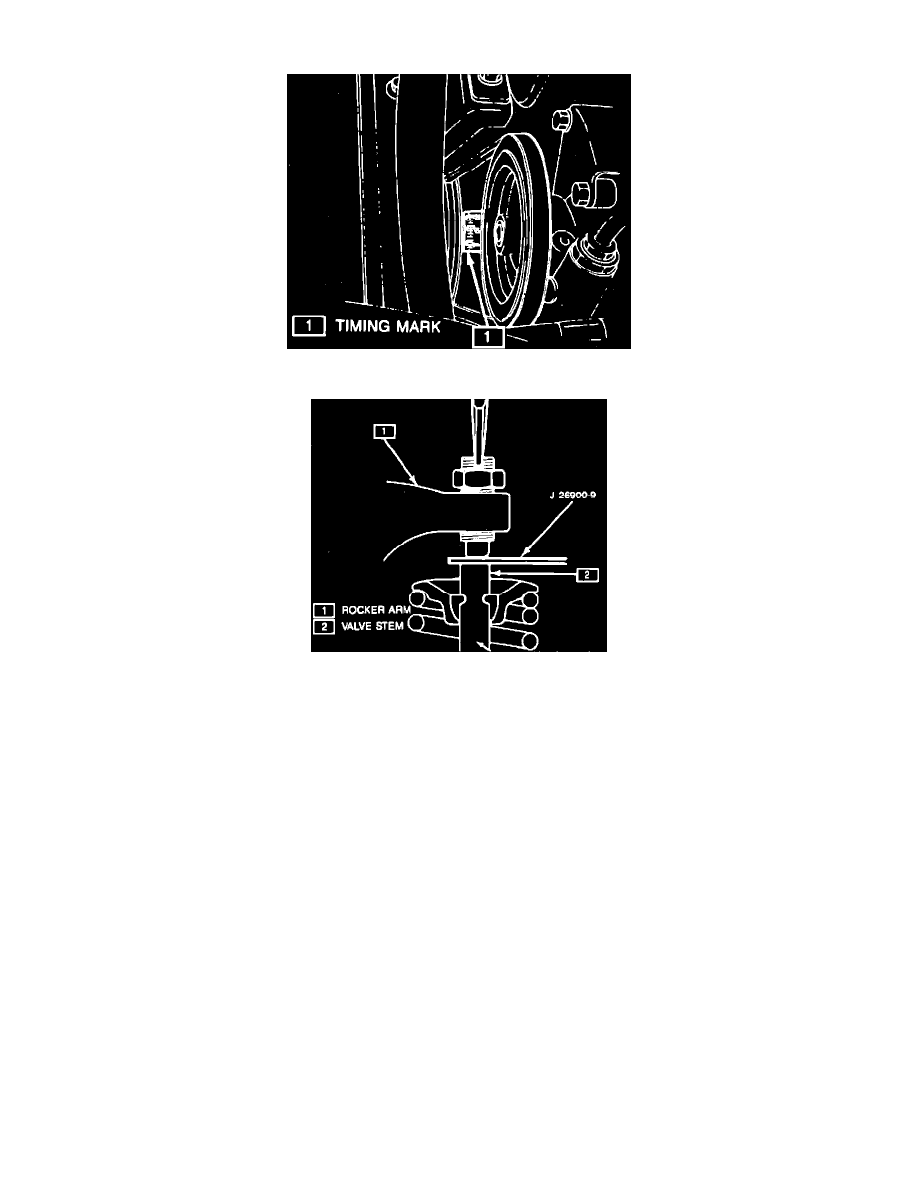
Fig. 13 SOHC Crankshaft Pulley Timing Mark
Fig. 14 SOHC Clearance Adjustment
1.
Set number one cylinder at TDC on the compression stroke, then turn crankshaft pulley to align its notched line with the 0 mark on timing cover.
2.
Ensure that valves on No. 1 cylinder have play and valves No. 4 cylinder do not. If not as specified, turn crankshaft pulley 360° and align the 0
mark on lower timing cover, Fig. 13.
3.
Measure valve lash between rocker arm and valve stem as follows:
a. Intake and exhaust valves on No. 1 cylinder.
b. Intake valve on No. 2 cylinder.
c. Exhaust valves on No. 3 cylinder.
4.
Valve lash should be 0.006 inch on intake and 0.010 on exhaust valves.
5.
If lash is not as specified, adjust valve lash by loosening adjustment screw locknut and turn adjustment screw until lash is within specifications,
Fig. 14.
6.
Tighten adjustment locknut, then rotate crankshaft 360° and measure lash as follows:
a. Intake and exhaust on No. 4 cylinder.
b. Intake valves on No. 3 cylinder.
c. Exhaust valves on No. 2 cylinder.
7.
Valve lash should be 0.006 inch on intake and 0.010 on exhaust valves.
8.
If lash is not as specified, adjust valve lash by loosening adjustment screw locknut and turn adjustment screw until lash is within specifications.
9.
Install cylinder head cover.