
Storm L4-1800cc 1.8L DOHC (1993)
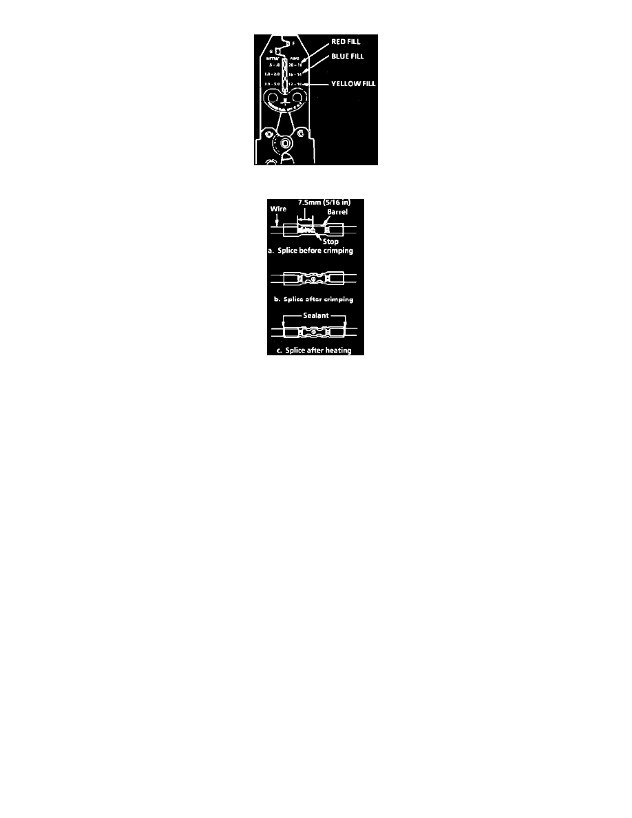
Fig. 13 Hand Crimp Tool
Fig. 14 Seal Splice Sequence
4. Select and Position the Splice Sleeve - according to wire size. The splice sleeves and tool nests are color coded. Using a crimp tool, position
the splice sleeve in the proper color nest of the hand crimp tool. Place the splice sleeve in the nest so that the crimp falls midway between the
end of the barrel and the stop.
The sleeve has a stop in the middle of the barrel to prevent the wire from going further. Close the hand crimper handles slightly to hold the
splice sleeve firmly in the proper nest.
5. Insert Wires into Splice Sleeve - until it hits the barrel stop and close the handles of the crimper tightly until the crimper handles open when
released. The crimper handles will not open until the proper amount of pressure is applied to the splice sleeve. Repeat steps 4 and 5 for
opposite end of the splice.
6. Shrink the Insulation around the Splice - using the Ultratorch J 38125-5 (follow instructions that accompany Ultratorch). Apply heat where
the barrel is crimped. Gradually move the heat barrel to the open end of the tubing, shrinking the tubing completely as the heat is moved along
the insulation. A small amount of sealant will come out of the end of the tubing when sufficient shrinking is achieved.
Splicing Copper Wire Using Splice Clips
PROCEDURE
The Splice Clip (included in the GM J 38125-A Terminal Repair Kit) is a general purpose wire repair device. It may not be acceptable for
applications having special requirements such as moisture sealing.
1. Open the Harness - by removing the tape. To avoid wire insulation damage, use a sewing "seam ripper" to cut open the harness (available from
sewing supply stores). If the harness has a black plastic conduit, simply pull out the desired wire.
2. Cut the Wire - by cutting as little wire off the harness as possible. You may need the extra length of the wire later if you decide to cut more wire
off to change the location of a splice. You may have to adjust splice locations to make certain that each splice is at least 40 mm (1-1/2") away from
other splices, harness branches or connectors.