
Storm L4-1800cc 18L DOHC (1993) | Starting System Diagram & Instructions | Page 3769
5. Tape the Cable - completely, using a winding motion. This tape will replace the section of the jacket you removed to make the repair.
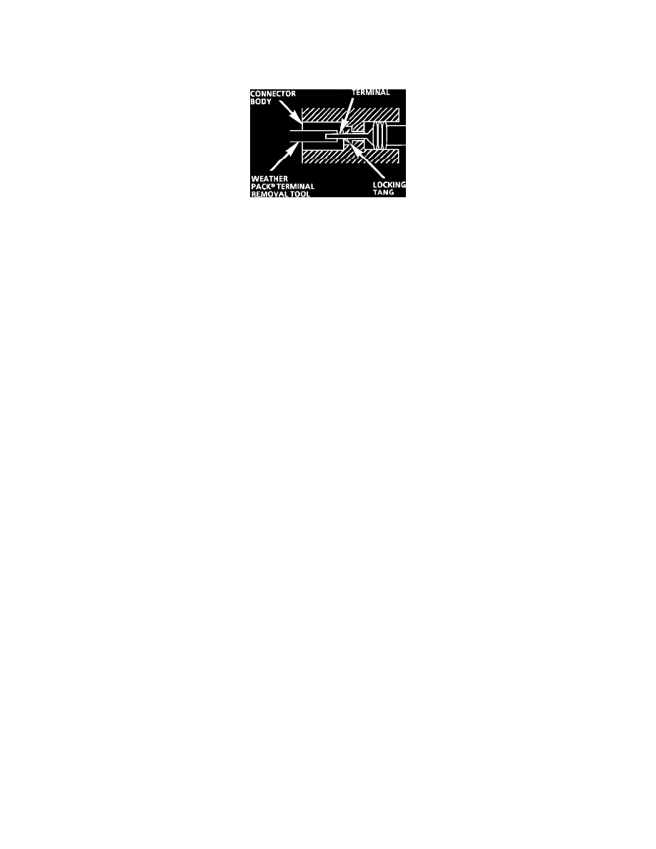
Weather Pack Connectors
Fig. 21 Typical Weather Pack Connector and Terminal
PROCEDURE
1
Separate the connector halves.
2. Open secondary lock. A secondary lock aids in terminal retention and is usually molded to the connector.
3. Grasp the lead and push the terminal to the forward most position. Hold the lead at this position.
4. Insert the Weather Pack terminal removal tool into the front (mating end) of the connector cavity until it rests on the cavity shoulder.
5. Gently pull on the lead to remove the terminal through the back of the connector.
NOTE: Never use force to remove a terminal from a connector.
6. Inspect the terminal and connector for damage. Repair as necessary.
7. Reform the lock tang and reseat terminal in connector body.
8. Close secondary locks and join connector halves.
Basic Troubleshooting Guide
TROUBLESHOOTING GUIDELINES
Without a basic knowledge of electricity, it will be difficult to use the diagnostic procedures contained in this section. You should understand the
basic theory of electricity and know the meaning of voltage, current (amps) and resistance (ohms). You should understand what happens in a
circuit with an open or a shorted wire. You should be able to read and understand a wiring diagram. The following four-step troubleshooting
procedure is recommended:
1. Check the Problem - by performing a System Check to determine a symptom. Don't waste time fixing part of the problem! Do not begin
disassembly or testing until you have narrowed down the possible causes.
2. Read the Electrical Schematic - and the Circuit Description text if you do not understand how the circuit should work. Check circuits that
share wiring with the problem circuit. (Shared circuits are shown on Power Distribution, Ground Distribution, Fuse Block Details and Light
Switch Details articles.) Try to operate the shared circuits. If the shared circuits work, then the shared wiring is OK. The cause must be within
the wiring used only by the problem circuit. If several circuits fail at the same time, chances are the power (fuse) or ground circuit is faulty.
3. Find the Fault and Repair - by narrowing down the possible causes:
^
Use the Troubleshooting Hints.
^
Make the necessary measurements or checks as given in the System Diagnosis.
^
Before replacing a component, check power, signal and ground wires at the component harness connector. If the checks and connections
are OK, the most probable cause is component failure.
4. Test the Repair - by repeating the System Check to verify the fault has been corrected and that no other faults were induced during the repair.
EXAMPLE
A customer brings in a vehicle and says that the HI beams do not work.
1. Perform a system check on the headlight circuit. You may discover that both LO beams operate. In "HI," you may notice that the HI Beam
Indicator comes on, but neither HI beam operates.