
Tracker 4x2 L4-1.6L SOHC TBI (1994)
Coolant Temperature Sensor/Switch (For Computer): Diagnostic Aids
Basic Troubleshooting Guide
TROUBLESHOOTING GUIDELINES
Without a basic knowledge of electricity, it will be difficult to use the diagnostic procedures contained in this section. You should understand the
basic theory of electricity and know the meaning of voltage, current (amps) and resistance (ohms). You should understand what happens in a
circuit with an open or a shorted wire. You should be able to read and understand a wiring diagram. The following four-step troubleshooting
procedure is recommended:
1. Check the Problem - by performing a System Check to determine a symptom. Don't waste time fixing part of the problem! Do not begin
disassembly or testing until you have narrowed down the possible causes.
2. Read the Electrical Schematic - and the Circuit Description text if you do not understand how the circuit should work. Check circuits that
share wiring with the problem circuit. (Shared circuits are shown on Power Distribution, Ground Distribution, Fuse Block Details and Light
Switch Details articles.) Try to operate the shared circuits. If the shared circuits work, then the shared wiring is OK. The cause must be within
the wiring used only by the problem circuit. If several circuits fail at the same time, chances are the power (fuse) or ground circuit is faulty.
3. Find the Fault and Repair - by narrowing down the possible causes:
^
Use the Troubleshooting Hints.
^
Make the necessary measurements or checks as given in the System Diagnosis.
^
Before replacing a component, check power, signal and ground wires at the component harness connector. If the checks and connections
are OK, the most probable cause is component failure.
4. Test the Repair - by repeating the System Check to verify the fault has been corrected and that no other faults were induced during the repair.
EXAMPLE
A customer brings in a vehicle and says that the HI beams do not work.
1. Perform a system check on the headlight circuit. You may discover that both LO beams operate. In "HI," you may notice that the HI Beam
Indicator comes on, but neither HI beam operates.
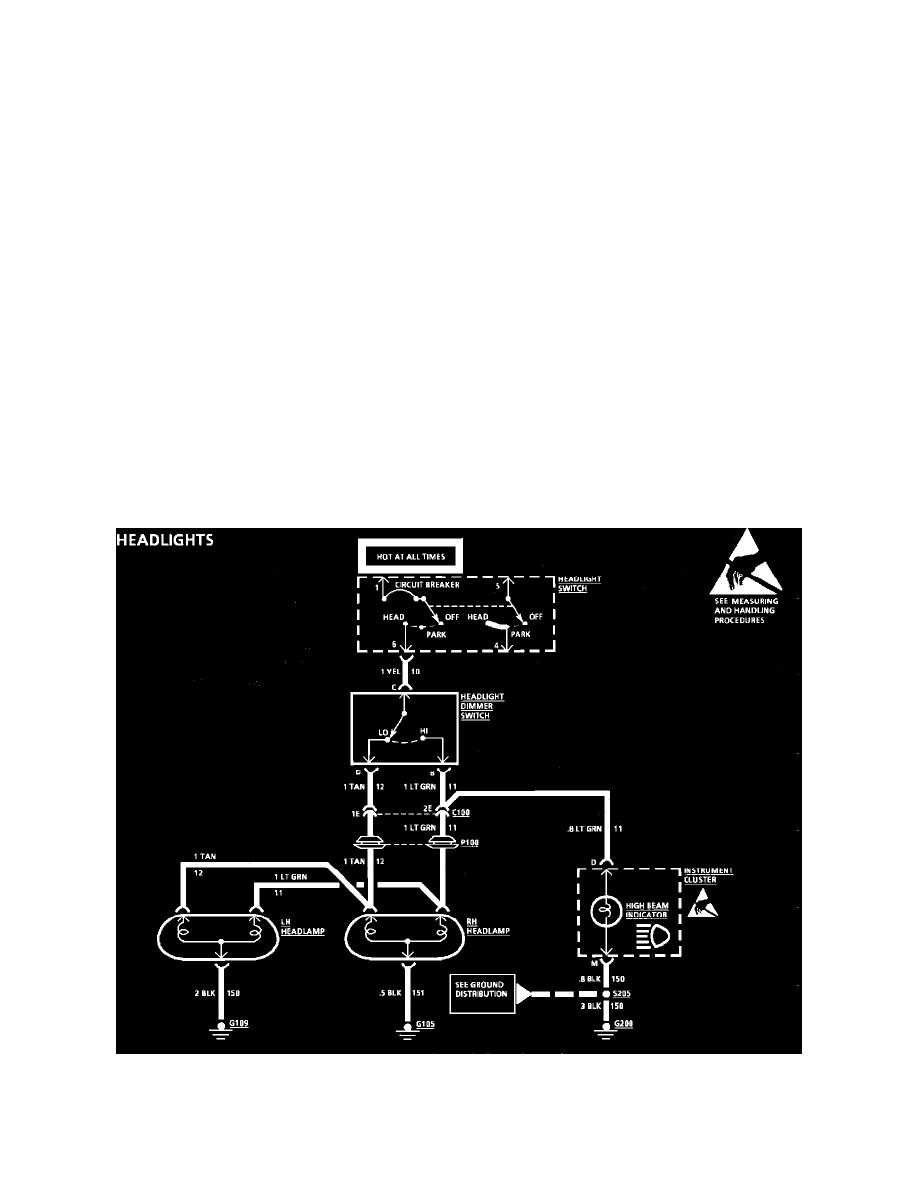
Fig. 1 Typical Headlights Schematic
2. Read the headlights electrical schematic, see Fig.5. This is the step that will save time and labor. Remember, it is essential to understand how a
circuit should work, before trying to figure out why it doesn't.