
Tracker 4x2 L4-1.6L SOHC TBI (1994)
provide a good path to ground.
Intermittents and Poor Connections
Most intermittents are usually caused by faulty electrical connections or wiring, although occasionally a sticking relay, solenoid, or loose ground
point can be a problem.
Handling and Measuring Procedures
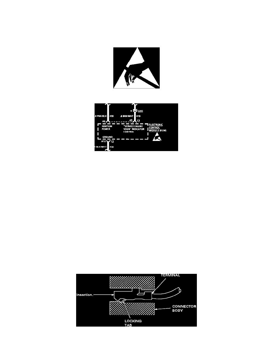
Fig. 1 ESD Symbol
Fig. 2 Typical Schematic W/ESD Symbol
ELECTROSTATIC DISCHARGE (ESD) SENSITIVE DEVICES
All ESD sensitive components are Solid State and the following information applies to them. The ESD symbol, Fig. 1, is used on schematics to
indicate which components are ESD sensitive, Fig. 2. When handling any electronic part, the service technician should follow the guidelines below
to reduce any possible electrostatic charge build-up on the service technician's body and the electronic part in the dealership. If it is not known
whether or not a component is ESD sensitive, assume that it is.
HANDLING PROCEDURES
1. Always touch a known good ground before handling the part. This should be repeated while handling the part and more frequently after sliding
across the seat, sitting down from a standing position or walking the distance.
2. Avoid touching electrical terminals of the part, unless so instructed by a written diagnostic procedure.
3. When using a voltmeter be sure to connect the ground lead first.
4. Do not open package until it is time to install the part.
5. Before removing the part from its package, ground the package to a known good ground on the vehicle.
MEASURING PROCEDURES
The circuits shown within the boxes are greatly simplified. Do not troubleshoot by measuring resistance at any terminal of these devices unless so
instructed by a written diagnostic procedure. Due to the simplification of the schematics, resistance measurements could be misleading, or could
lead to electrostatic discharge.
Pull-to-Seat Connectors
Figure 20 - Typical Pull-To-Seat Connector