
Tracker 4x2 L4-1.6L SOHC TBI (1994)
Fuel Flow Circuit
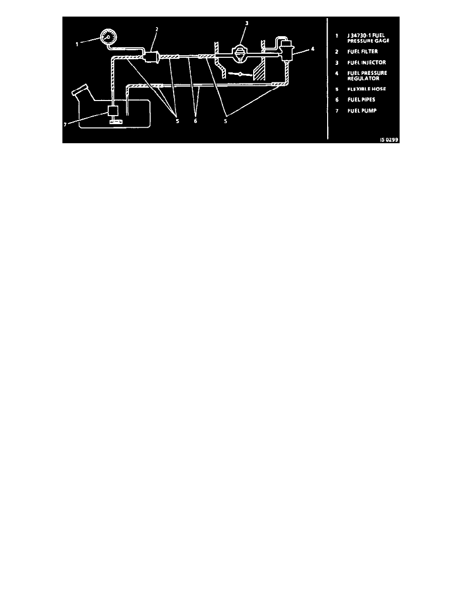
CIRCUIT DESCRIPTION
When the ignition switch is turned to the "ON" position, the Engine Control Module (ECM) will energize the fuel pump relay for 3 seconds,
allowing for fuel pump operation. If the engine is being cranked, or is running, the fuel pump will continue to operate, as long as the ECM is
receiving ignition references pulses. If the ignition reference pulses are not detected, the fuel pump will stop after 3 seconds.
The fuel pump will deliver fuel through the fuel filter to the fuel injector and fuel pressure regulator, where the system pressure is controlled at
240-280 kPa (34-41 psi). Excess fuel is returned to the fuel tank by means of a fuel return pipe.
TEST DESCRIPTION Number(s) below refer to circled number(s) on the diagnostic chart.
1. Checks to see if fuel system pressure is within specifications.
2. Checks fuel feed pipe and hose for leaks.
3. Checks for faulty fuel pump or faulty pressure regulator.
4. Checks for a leaky fuel injector or throttle body or a faulty fuel pressure regulator.
5. Checks for leaks at the fuel pump hose connections, for a faulty fuel pump or a faulty fuel pressure regulator.
6. Checks for restricted fuel feed pipe, faulty fuel filter or restricted return fuel pipe.
DIAGNOSTIC AIDS
Improper fuel system pressure can result in one of the following conditions:
-
Cranks, but will not run.
-
Cuts out, may feel like ignition problem.
-
Poor fuel economy, loss of power.
-
Hard starts.