
Tracker 4x2 L4-1.6L VIN 6 (1995)
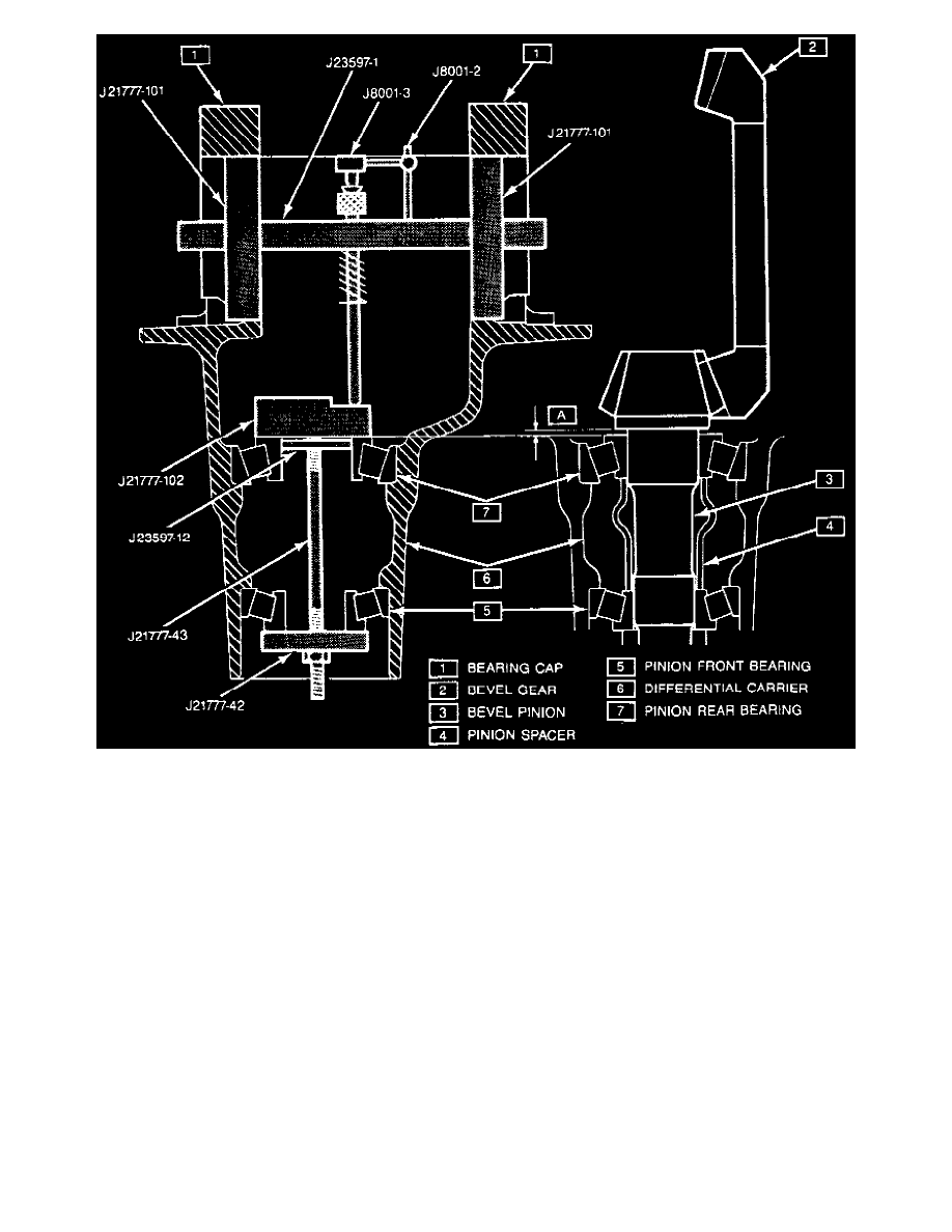
Fig. 8 Pinion Depth Measurement.
b. While holding pinion bearings in position, install a J-21777-102 gauge plate, J23597-12 inner pilot washer, J-21777-43 stud and nut and a
J-21777-42 outer pilot washer, or equivalents as shown in Fig. 8.
c. Hold stud stationary and torque locknut to 18 inch lbs.
d. Rotate gauge plate tool No. J-21777-102 or equivalent 25 revolutions to seat pinion bearings.
e. Torque locknut again to 18 inch lbs. to ensure bearings are seated.
f.
Install two side bearing discs part No. J-21777-01, or equivalent, on side bearing bores using arbor tool No. J-23597-1, or equivalent.
g. Rotate gauge plate tool No. J-21777-102 until gauging areas are parallel with two side bearing discs.
h. Position dial indicator rod over the 97 mm portion of the gauging plate.
i.
Connect dial indicator tool No. J-8001 or equivalent to arbor tool No. J-23597-1 and position gauge shaft over dial indicator rod.
j.
Install side bearing caps and torque bolts to 63 ft. lbs.
k. Set dial indicator to zero.
l.
Slowly rotate arbor on 97 mm step of gauge plate to determine the point of greatest deflection. Reset dial indicator to zero.
m. Slowly rotate arbor until dial indicator is no longer in contact with gauge plate.