
Tracker 4x4 L4-1.6L VIN 6 (1995)
Distributor: Testing and Inspection
Checking Camshaft Position (CMP) Sensor
DISTRIBUTOR DISASSEMBLY, TEST AND REASSEMBLY PROCEDURE
TOOL REQUIRED
J 34029-A Digital Multimeter
REMOVE OR DISCONNECT
IMPORTANT: Make sure that the ignition switch is in the "LOCK" position.
1. Two screws and distributor cap from distributor.
2. Distributor rotor and signal rotor cover from distributor housing.
MEASURE
Probe ECM connector C2 with a digital multimeter from cavity "3" to ground.
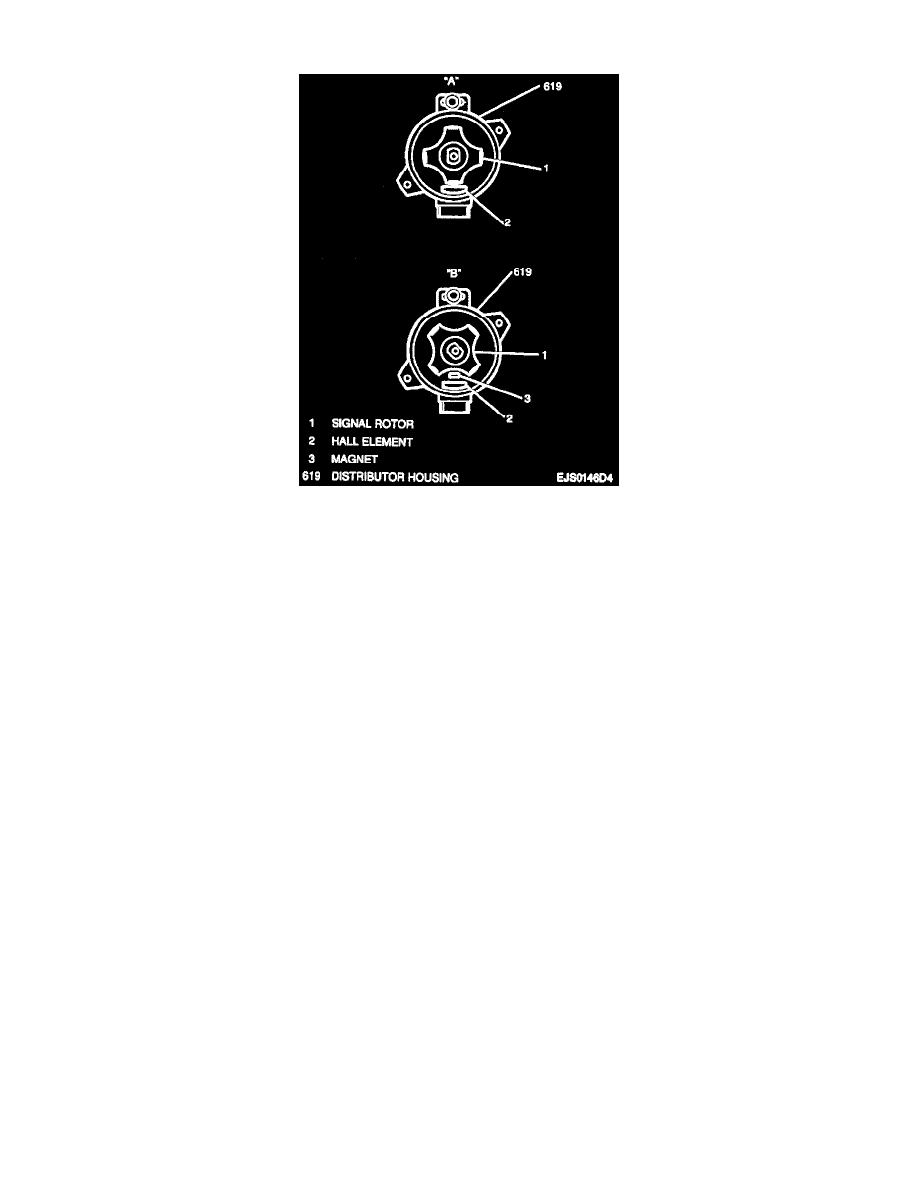
A. Turn ignition switch to "ON." Check voltage with signal rotor between hall element and magnet "A" (refer to accompanying image).
^
If voltage is 3 to 5 volts, proceed with Step B.
^
If voltage is not 3 to 5 volts, refer to Computers and Control Systems / System Diagnosis for further diagnostic procedures. See: Powertrain
Management/Computers and Control Systems/Testing and Inspection
B. Check voltage without the signal rotor between the hall element and magnet "B."
^
If voltage is 0 to 1 volt, then the Camshaft Position (CMP) sensor is operating normally. Turn ignition switch to "LOCK."
^
If voltage is not 0 to 1 volt, refer to Computers and Control Systems / System Diagnosis for further diagnostic procedures.
INSTALL OR CONNECT
1. Signal rotor cover and distributor rotor to distributor housing.
2. Distributor cap to distributor; secure with two screws.