
Tracker 4x4 L4-1.6L VIN 6 (1995)
Throttle Position Sensor: Adjustments
TOOL REQUIRED
J39200 Digital Multimeter
REMOVE OR DISCONNECT
1. Negative (-) battery cable.
2. Throttle Position (TP) sensor electrical connector.
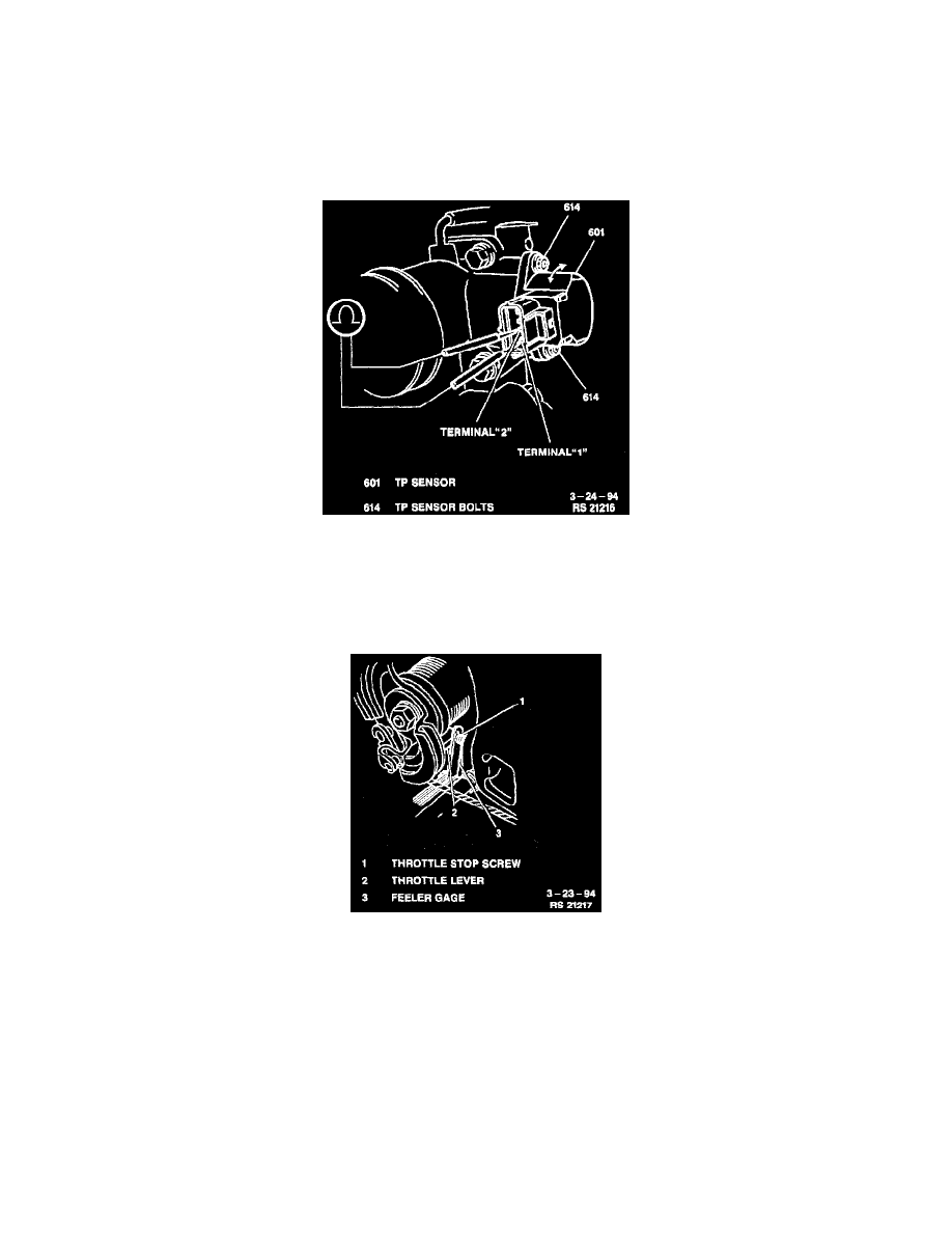
^
Loosen TP sensor mounting bolts.
Measuring TP Sensor Resistance
ADJUST
A. Connect a DVOM to TP sensor connector terminal "1" to "2" (TP sensor side). Measure resistance.
NOTICE: Throttle valve must be closed.
Inserting Feeler Gauge
B. Insert a 0.65 mm (0.026-inch) feeler gage between throttle stop screw and throttle lever (refer to image) and with retaining screws loosely
installed, turn TP sensor fully counterclockwise, then slowly clockwise gradually to find position where ohmmeter reading changes from continuity
to no continuity. Tighten TP sensor bolts to 2.5 - 4.5 Nm (22.8 - 38.4 lb. in.).
C. Remove feeler gage. DVOM should still indicate continuity.
D. Insert 0.8 mm (0.037-inch) feeler gage between throttle stop screw and throttle lever. DVOM should now indicate an open circuit.
E. Insert 0.5 mm (0.020-inch) feeler gage between throttle stop screw and throttle lever. DVOM should indicate continuity. If steps C, D or E are
unsatisfactory, return to step A and repeat entire procedure.
INSTALL OR CONNECT
1. TP sensor electrical connector.
2. Negative (-) battery cable. Tighten Negative (-) battery cable-to-negative (-) battery terminal retainer to 15 Nm (11 lb. ft.).