
Tracker 4x4 L4-1.6L VIN 6 (1995)
Throttle Position Sensor: Testing and Inspection
Throttle Position Sensor Output Check
THROTTLE POSITION SENSOR CHECK
TOOL REQUIRED
J 39200 Digital Multimeter
REMOVE OR DISCONNECT
1. Negative (-) battery cable.
2. Throttle Position (TP) sensor electrical connector.
MEASURE
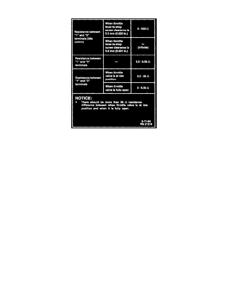
Throttle Position (TP) sensor resistance according to the chart in the accompanying image. If TP sensor resistance is not within the specified
ranges, adjust or replace TP sensor. Refer to either Adjustments or Service and Repair for the appropriate procedure.
INSTALL OR CONNECT
1. TP sensor electrical connector.
2. Negative (-) battery cable. Tighten Negative (-) battery cable-to-negative (-) battery terminal retainer to 15 Nm (11 lb. ft.).