
Tracker 4x4 L4-1.6L VIN 6 (1995)
Valve Clearance: Adjustments
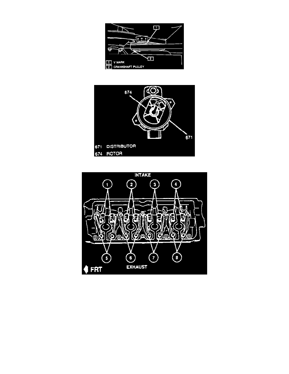
Crankshaft Pulley Timing Mark
Fig. 20 Distributor Rotor Alignment, Cylinder No. 1 TDC.
Fig. 21 Valve Identification.
1. Disconnect battery ground cable, then remove cylinder head cover. Refer to Valve Cover / Service and Repair. See: Engine, Cooling and
Exhaust/Engine/Cylinder Head Assembly/Valve Cover/Service and Repair
2. Rotate crankshaft pulley clockwise until "V" mark on pulley is aligned with "O" calibrated on timing belt cover, Fig. 17.
3. Remove distributor cap, ensure ignition rotor is in No. 1 position, Fig. 20, at TDC of compression stroke, if rotor is out of place turn crankshaft
pulley clockwise one revolution 360 degrees.
4. Using a feeler gauge, measure valve lash at valves 1, 2, 5, and 7 Fig. 21.
5. Turn adjusting screw until lash is within specification. Hold adjusting screw in place and tighten locknut to specifications.
6. Rotate crankshaft one revolution clockwise and check valve lash at valves 3, 4, 6 and 8, Fig. 21.
7. Turn adjusting screw until lash is within specification, hold adjusting screw in place and tighten locknut to specification.
8. Install distributor cap on distributor.
9. Install cylinder head cover. Refer to Valve Cover / Service and Repair.
10. Connect battery ground cable.