
Tracker 4x4 L4-1.6L VIN 6 (1995)
Engine Control Module: Description and Operation
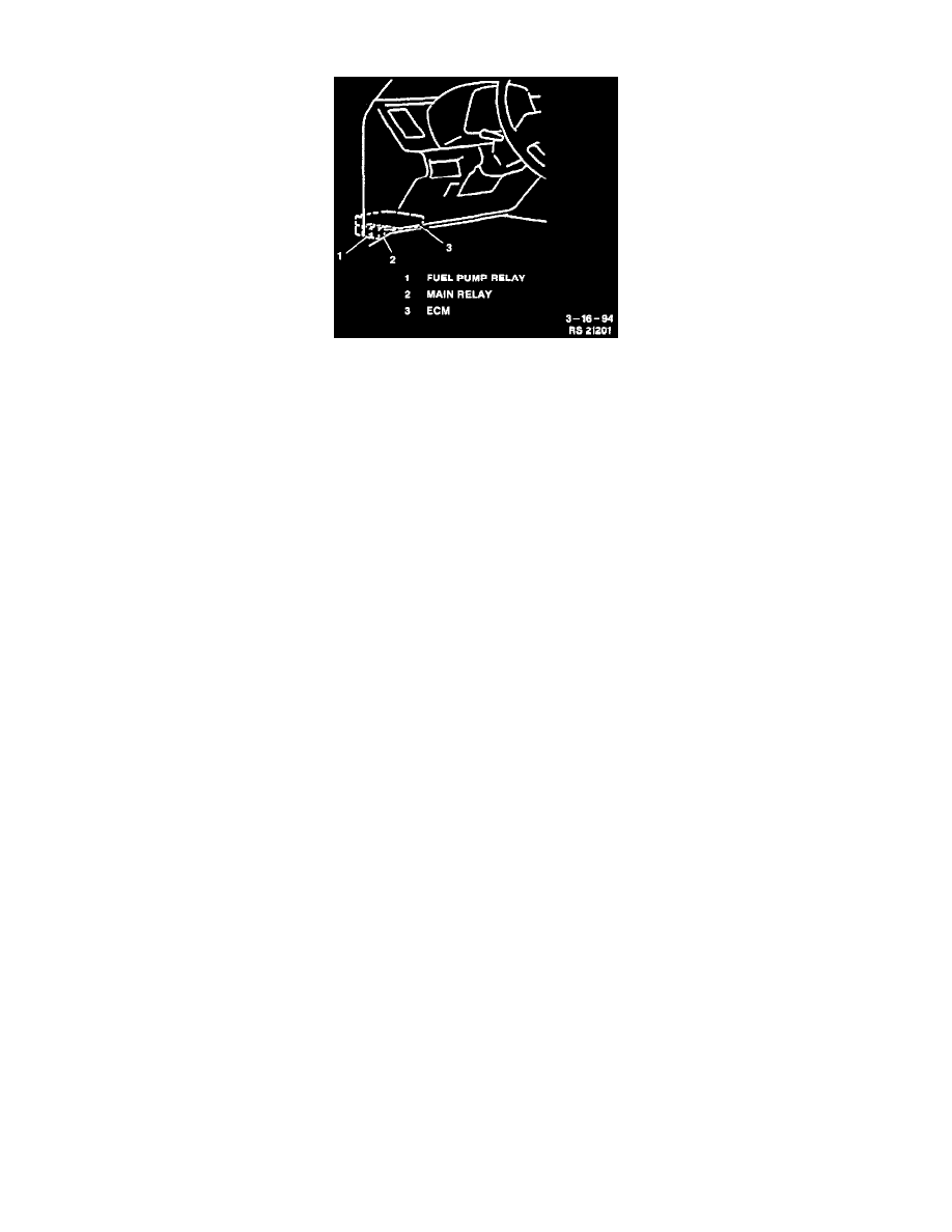
Component Location
ENGINE CONTROL MODULE
DESCRIPTION
The Engine Control Module (ECM) is a precision unit consisting of a one chip microcomputer, Analog/Digital (A/D) converter and an
Input/Output (I/O) unit. It is an essential part of the electronic control system, for its functions include not only such major functions as to control
the fuel injector, Idle Air Control (IAC) valve, fuel pump relay, etc., but also a self-diagnosis function and a fail-safe function as described in the
following section. The ECM is installed below the instrument panel left of the steering column.
SELF-DIAGNOSIS FUNCTION
The Engine Control Module diagnoses troubles which may occur in the system when the ignition switch is in the "ON" position with the engine
running. The ECM indicates a malfunction by lighting the Malfunction Indicator Lamp (MIL) when a fault occurs in any of the following systems:
^
Heated Oxygen Sensor (HO2S).
^
Engine Coolant Temperature (ECT) sensor.
^
Throttle Position (TP) sensor.
^
Vehicle Speed Sensor (VSS).
^
Intake Air Temperature (IAT) sensor.
^
Mass Air Flow (MAF) sensor.
^
Ignition fail-safe signal.
^
Camshaft Position (CMP) sensor.
^
Idle switch circuit.
^
Exhaust Gas Recirculation (EGR) system including EGR temperature sensor.
^
Central Processing Unit (CPU) of ECM.
OPERATION
The ECM and the MIL operate as follows:
MIL Circuit Check
The MIL lights when the ignition switch is turned to the "ON" position (engine not running) with the diagnostic request terminal not grounded,
regardless of the condition of the Sequential Multiport Fuel Injection (SFI) system. This is only to check the MIL circuit.
Fault Detection
Once the engine is started and no faults are detected by the ECM, the MIL goes out. When the ECM detects a malfunction in one of the above
areas, it lights the MIL to warn the driver of the occurrence of a fault. At the same time it stores a Diagnostic Trouble Code (DTC) in the ECM
memory. If the cause of the malfunction is no longer detected by the ECM, the MIL will go out, but the corresponding DTC will be stored in the
ECM memory.
MIL Flashes DTCs
The ECM will indicate DTCs that are stored in its memory by means of flashing the MIL at the time of inspection (i.e., when diagnostic request
terminal is grounded and ignition switch is turned to the "ON" position) or through the Tech 1 scan tool.
Stored DTCs
Any DTCs that occur with the engine running are stored in the ECM memory even if the fault was only temporary and disappeared immediately.
The ECM memory is not erased unless the power to the ECM is shut "OFF" for 20 seconds or longer.