
Tracker 4x4 L4-1.6L VIN 6 (1995)
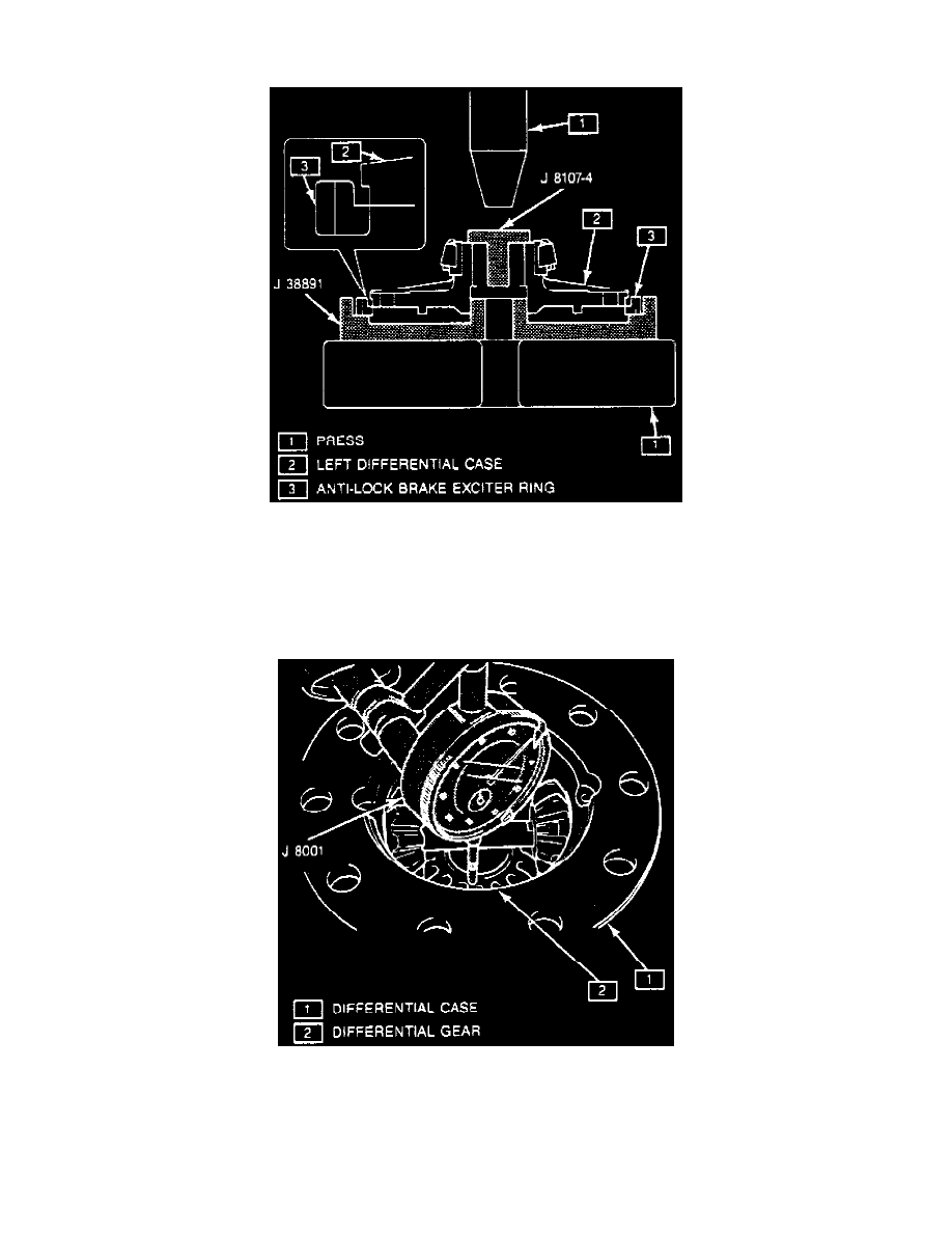
1. Using exciter ring installer tool No. J-38891, differential side bearing remover tool No. J-8107-4 and a suitable press or equivalents, install
anti-lock brake exciter ring to differential left case as follows:
Fig. 14 Rear Wheel Anti-Lock Brake Exciter Ring Installation.
2. Install rear wheel anti-lock brake exciter ring using exciter ring installer tool No. J-38891, or equivalent, a differential side bearing installer tool
No. J-8107-04, or equivalent and a press, Fig. 14. Pressure exerted on exciter ring should not exceed 1102 lbs. If more than 1102 lbs. of
pressure is needed for press fitting, left case and exciter ring are probably not evenly aligned. Remove from press and repeat procedure.
3. Install rear speed sensor and torque bolt to 17 ft. lbs.
4. Install differential pinion gears, thrust washers, cross shafts and right side gear with selective shim in differential case.
Fig. 15 Right Side Gear Endplay Measurement.
5. Measure differential right side gear endplay using a suitable dial indicator, Fig. 15. If end play is not .005-0.014 inch, select shim to obtain correct
end play.
6. Install cross shaft spring pins into differential case until pins are flush with differential case surface.
7. Install left differential side gear, selective shim and ring gear into case.