
Tracker 4x4 L4-1.6L VIN 6 (1995)
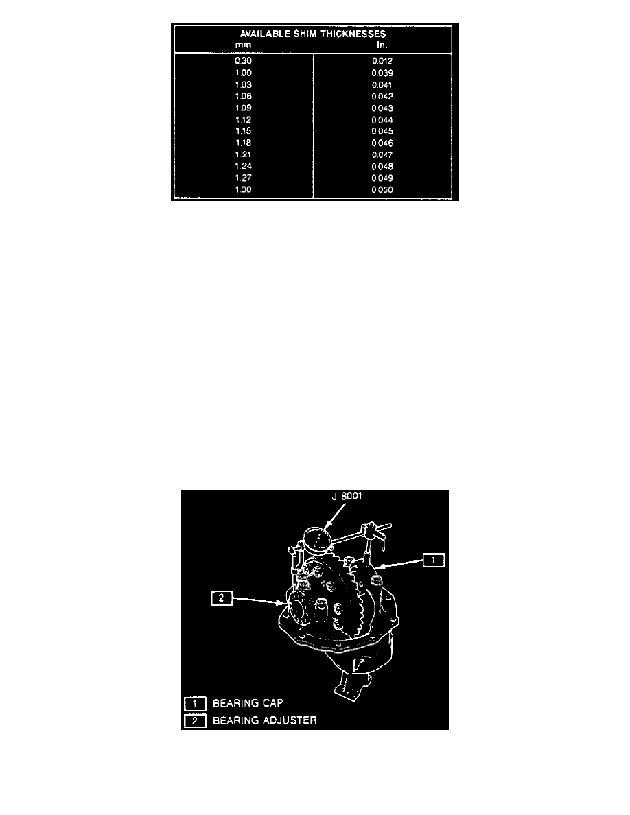
Fig. 16 Pinion Depth Selective Shims.
n. Record dial indicator reading. This reading indicates the selective shim required for correct pinion depth. Refer to selective shim chart Fig. 16
for correct shim.
16. Install pinion selective shim on pinion gear shaft.
17. Using bearing installer tool No. J-6133-01, or equivalent, and a press pinion bearing on pinion gear shaft.
18. Install new collapsible spacer on pinion gear shaft.
19. Install pinion outer bearing into differential carrier.
20. Lubricate pinion oil seal with part No. 1050010, or equivalent, then install pinion oil seal using seal installer tool No. J-25273, or equivalent, and a
plastic hammer.
21. Install pinion flange, washer and flange nut using pinion flange holder tool No. J-8614-01, or equivalent. Tightening flange nut will preload the
pinion bearings. Exceeding preload specification will compress the collapsible spacer too far and require the installation of a new spacer.
Adjust pinion bearing preload to 11 ft. lbs. starting torque not rotating torque. Measure pinion bearing preload again after rotating
pinion several times to ensure bearings have been seated. If preload has been reduced, reset preload to specification.
22. Install side bearing races on differential side bearings.
23. Install differential case on differential carrier.
24. Install side bearing adjusters, then align bearing caps with marks made during disassembling and torque cap bolts to 65 ft.lbs.
25. Adjust backlash and differential bearing preload as follows:
a. Left bearing adjuster nut is located on ring gear side of carrier, right bearing adjuster nut is located on pinion gear side of carrier.
b. Using spanner wrench tool No. J-37760, or equivalent, loosen right adjuster nut until it does not contact side bearing race.
c. Using spanner wrench, tighten left adjuster nut until ring gear is fully engaged into pinion gear with zero backlash.
d. Ensure right adjuster nut is still not in contact with side bearing race.
e. Rotate pinion gear to ensure there is no binding.
Fig. 17 Side Bearing Preload Dial Indictor Setting.
f.
Install dial indicator to differential carrier as shown in Fig. 17.
g. Using spanner wrench too No. J-37760, or equivalent, tighten right adjuster nut until it contacts side bearing race.