
Tracker 4x4 L4-1590cc 1.6L (1993)
Fuel System Circuit
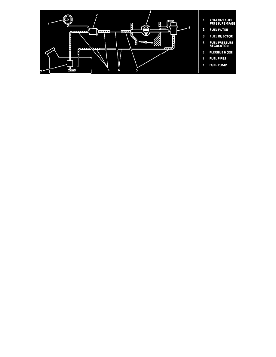
CIRCUIT DESCRIPTION:
When the ignition switch is turned to the "ON," position the Electronic Control Module (ECM) will energize the fuel pump relay for 3 seconds, allowing
for fuel pump operation. If the engine is being cranked, or is running, the fuel pump will continue to operate, as long as the ECM is receiving ignition
reference pulses. If the ignition reference pulses are not detected, the fuel pump will stop after 3 seconds. The fuel pump will deliver fuel through the fuel
filter to the fuel injector and fuel pressure regulator, where the system pressure is controlled at 240-280 kPa (34-41 psi). Excess fuel is returned to the
fuel tank by means of a fuel return pipe.
TEST DESCRIPTION: The numbers below refer to circled numbers on the diagnostic chart.
1.
Checks to see if fuel system pressure is within specifications.
2.
Checks fuel feed pump and hose for leaks.
3.
Checks for faulty fuel pump or faulty pressure regulator.
4.
Checks for a leaky fuel injector or throttle body or a faulty fuel pressure regulator.
DIAGNOSTIC AIDS:
Improper fuel system pressure can result from one of the following conditions:
1.
Cranks, but won't run.
2.
Cuts out, may feel like ignition problem.
3.
Poor fuel economy, loss of power.
4.
Hard starts.
The following procedure outlines the installation and removal of the Fuel Pressure Gage Assembly. Make certain to observe all "Cautions" while
performing this procedure.
REQUIRED TOOLS:
Port Fuel Pressure Gauge ....................................................................................................................................................................................... J 34730-1
Fuel Rail Adaptor ...................................................................................................................................................................................................... J 38347
CAUTION: To reduce the risk of fire and personal injury, relieve fuel system pressure before disconnecting the fuel lines. Loosen the fuel filler cap to
relieve tank pressure. Remove the circuit opening relay, located under the console in front of the shift lever. Crank the engine and allow it to run until it
stalls. Engage the starter for 30 seconds. Use a shop towel to collect fuel during the fuel line disconnection, place the towel in an approved container.
FUEL PRESSURE GAUGE INSTALLATION:
1.
Loosen fuel filler cap to relieve fuel tank pressure.
2.
Remove fuel pump relay.
3.
Crank engine and allow to stall. Crank engine for an additional 3 seconds to assure relief of any remaining fuel pressure.
4.
Disconnect negative battery cable.
5.
Raise vehicle.
6.
Remove fuel filter inlet hose plug. Use a shop towel to catch any remaining fuel that may leak.
7.
Install J 37746 fuel pressure gauge adapter to fuel filter inlet union bolt.
8.
Install J 34730-1 fuel pressure gauge to J 37746 fuel pressure gauge adapter.
9.
Lower vehicle.