
Tracker 4x4 L4-1590cc 1.6L (1993)
Valve Clearance: Adjustments
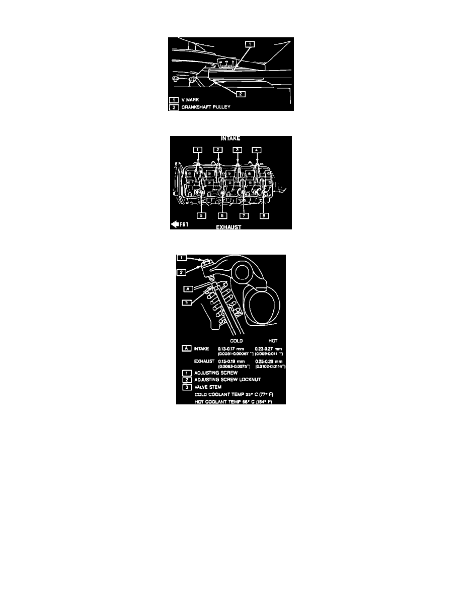
Fig. 21 Crankshaft Pulley Timing Mark
Fig. 22 Valve Identification
Fig. 23 Valve Lash Specifications
Valve lash refers to the gap between the rocker arm adjusting screw and the valve stem. Adjust valve lash as follows:
1.
Remove cylinder head cover as outlined under COMPONENT REPLACEMENT AND REPAIR/CYLINDER HEAD COVER.
2.
Turn crankshaft pulley clockwise until ``V'' mark on pulley is aligned with ``0'' mark on timing belt cover, Fig. 21.
3.
Remove distributor cap and ensure rotor is positioned at No. 1 cylinder spark plug wire.
4.
Check valve lash at valves 1, 2, 5 and 7, Fig. 22.
5.
If valve lash is out of specification shown in Fig. 23, adjust by turning the adjusting screw after loosening the locknut.
6.
After adjustment has been made, torque locknut to 11-13.5 ft. lbs.
7.
Rotate crankshaft 1 revolution (360°) clockwise and repeat steps 5 and 6 for valves 3, 4, 6 and 8.
8.
Install cylinder head cover, distributor cap and air intake case.