
Acadia FWD V6-3.6L (2007)
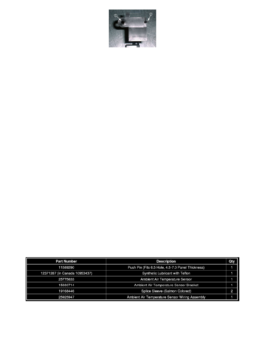
9. Hold the ambient air temperature sensor (with the bracket attached) on the front bumper bar at the previously marked position and use a center
punch to mark the location for the guide pin hole (callout 2 in the illustration above). Drill a 6.5 mm (1/4 in) hole in the front bumper beam for the
guide pin.
10. Insert the sensor bracket guide pin into the hole. Hold the new ambient air temperature sensor in position and use a center punch to mark the hole
location (at callout 1 above) for the sensor retaining Push Pin, P/N 11589290. Drill a 6.5 mm (1/4 in) hole for the push pin.
11. Apply Synthetic Lubricant with Teflon, P/N 12371287 (in Canada, 10953437), or equivalent, to the holes in the front bumper beam for rust
prevention.
12. Apply a piece of two-sided tape to the top of the ambient air temperature sensor bracket. This will help retain the new ambient air temperature
sensor.
13. Install the new ambient air temperature sensor onto the front bumper beam.
14. Cut the connector from the end of the wiring harness for the ambient air temperature sensor.
15. Splice the Ambient Air Temperature Sensor Jumper Harness, P/N 25925947 onto the wiring harness using two wire splices, P/N 19168446.
16. Route the jumper harness down along the left side of the radiator assembly to the new ambient air temperature sensor location. Use wire ties to
secure the jumper harness as necessary. Make sure that the jumper harness is secured away from the engine cooling fan. Connect the jumper
harness to the ambient air temperature sensor.
17. Install the front bumper fascia.
18. Install the front wheelhouse liners.
19. Install the front tire and wheel assemblies.
20. Install the front compartment sight shield.
21. Close the hood.
Important
Be careful to make the proper selection from the list of available calibrations. Verify the RPO Codes. New calibrations are available for vehicles
with or without the ambient air temperature sensor being relocated.
22. Reprogram the HVAC Control Module with the latest software available on TIS2WEB. Refer to the HVAC Control Module Programming and
Setup procedure in SI for more information.
23. Verify proper operation of the ambient air temperature sensor.
Parts Information
Warranty Information