
C 1500 Suburban 2WD V8-5.7L VIN R (1996)
Differential Carrier: Service and Repair
Corporate and Eaton
Disassembly
Axle can be disassembled either in or out of vehicle. If axle is disassembled in vehicle, it may be necessary to remove spare tire and/or
disconnect shock absorbers to provide clearance for differential case removal. If axle assembly is allowed to hang, care must be taken not
to damage or stretch flexible brake hose between axle and frame mounted lines.
1. Loosen rear cover bolts, break cover loose at bottom and drain lubricant, then remove cover and gasket.
2. Mount suitable dial indicator on bearing cap, and measure and record ring gear and pinion backlash.
3. Remove axles. Refer to
Drive Axles, Bearings and Joints / Axle Shaft, Conventional Fixed/Floating / Service and Repair. See: Drive Axles,
Bearings and Joints/Axle Shaft Assembly
4. Remove outer wheel bearings and seals, then pinion shaft lock screw and pinion shaft.
5. Roll pinion gears out of case with pinion thrust washers, then remove side gears and side gear thrust washers. Mark gears and differential case as
left and right.
6. Remove differential bearing cap bolts, then bearing caps. Mark caps and housing as left and right.
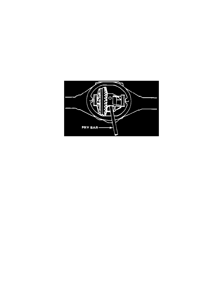
Fig. 1 Differential Case Assembly Removal.
7. Pry differential case assembly from axle housing, taking care not to damage cover gasket surface. Remove differential carrier by prying case from
axle housing at differential window,
Fig. 1.
8. Remove bearing outer races, shims and spacers. Mark races and bearings as left and right, then place them with cages.
9. Remove differential side bearings using tool No. J-8107-2 and tool No. J-22888 or their equivalents.
10. Remove ring gear bolts, then ring gear.
Ring gear bolts are left handed threads. Do not pry ring gear from case as damage to gear and case
will result. Drive ring gear off with a brass drift, if necessary.
11. Check drive pinion preload using suitable torque wrench and record reading. Inspect pinion assembly for looseness by moving it back and forth,
looseness will indicate excessive bearing wear.
12. Hold driveshaft yoke with suitable tool and remove pinion nut and washer.
13. Remove driveshaft yoke with suitable puller.
14. Thread pinion nut halfway onto pinion, temporarily install rear cover, then tap pinion from bearings using large hammer and soft drift.
15. Remove pinion seal and front pinion bearing from housing.
16. Remove rear cover, then the drive pinion and rear bearing assembly from housing.
17. Discard collapsible preload spacer, press rear bearing from pinion, then remove depth adjusting shim and retain for assembly adjustment.
18. Remove bearing cups from axle housing using a hammer and punch in slots provided. Work cups out of housing evenly by moving punch back and
forth between sides of cup.
19. Inspect components. Refer to
Cleaning and Inspection. See: 7 1/2 - 8 5/8 Inch Ring Gear/Cleaning & Inspection
Assembly