
C 1500 Suburban 2WD V8-5.7L VIN R (1996)
3.
Remove differential pinions and thrust washers, side gears and side gear thrust washers, noting installation position for assembly. Keep thrust
washers with respective gears.
4.
Remove ring gear bolts, then the ring gear, driving ring gear from case using suitable drift and hammer.
Ring gear bolts have lefthand threads.
Do not pry between ring gear and case, as mating surfaces will be damaged.
5.
Inspect components. Refer to
Cleaning and Inspection. See: 7 1/2 - 8 5/8 Inch Ring Gear/Cleaning & Inspection
6.
Install thrust washers on side gears and mount side gears in case.
Lubricate all components with specified gear lubricant prior to assembly.
7.
Position one differential pinion (less thrust washer) between side gears and rotate gears until pinion is directly opposite case loading opening.
8.
Install other pinion with pinion shaft holes aligned, then rotate side gears and ensure that pinions align with shaft openings in case.
9.
When pinions are properly aligned, rotate pinions toward loading opening just enough to allow thrust washer installation and install washers.
10.
Align pinions with shaft opening in case, insert pinion shaft through case, install new lock bolt and torque bolt to 20 ft. lbs.
11.
Ensure that ring gear and case mating surfaces are clean and free from burrs, mount gear on case, install 2 new retaining bolts at opposite sides of
gear and alternately tighten bolts to draw gear on case.
12.
Install remaining ring gear bolts hand tight and ensure that gear is squarely seated on case.
Always use new bolts of proper type when installing
ring gear. Do not reuse old bolts.
13.
Alternately torque ring gear bolts to 80-95 ft. lbs. on models with 7 1/2 inch ring gear, 80 ft. lbs. on models with 8 1/2 inch ring gear or 60 ft. lbs.
on models with 8 5/8 inch ring gear.
14.
Press side bearings onto case. If old bearings are reused, ensure that bearings are installed in original position.
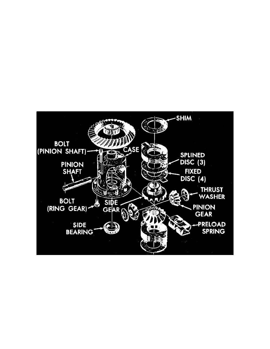
Limited Slip
Fig. 3 Chevrolet disc type limited slip differential exploded view
1.
Remove ring gear and side bearings, then remove pinion shaft,
Fig. 3.
2.
Using a brass drift drive the preload spring from the case.
3.
Support an axle shaft in a vise, and slide the case into the shaft, then turn the case to remove both pinions and thrust washers.
4.
Remove the case from the axle shaft, then remove both side gears, clutch packs and shims. Mark the gears, clutch packs and shims for
reinstallation in same position.
5.
Inspect gears, bearings and case. Refer to
Cleaning and Inspection. See: 7 1/2 - 8 5/8 Inch Ring Gear/Cleaning & Inspection
6.
Inspect clutch plates and spacers, and replace if worn or overheated.
7.
Replace preload spring if force required to compress spring to height of 1 5/16 inches is not 270-330 lbs.
8.
Lubricate the clutch discs and plates with limited slip lubricant.
9.
Alternately position clutch plates and discs on a side gear, beginning and ending with a clutch plate,
Fig. 3.
10.
Position the side gear, clutch pack and original shim into the case.
11.
Install both pinion gears and thrust washers into the case, and install the pinion shaft.