
C 1500 Truck 2WD V6-262 4.3L VIN Z (1992)
Brake Rotor/Disc: All Technical Service Bulletins
Steering - Noise At Full Lock
GMC NUMBER: 92-3C-111
GROUP: 3C Front Suspension
DATE: August 1992
CORPORATE NUMBER: 863301R
SUBJECT:
NOISE AT FULL STEERING LOCK (PROVIDE ADDITIONAL LOWER CONTROL ARM TO BRAKE ROTOR CLEARANCE)
MODELS:
1988 AND 1992 C TRUCKS
THIS BULLETIN CANCELS AND REPLACES GMC TRUCK SERVICE BULLETIN 88-T-24, DATED JULY 1987 (CORPORATE NUMBER
863301) TO INCLUDE THE 1992 MODEL YEAR. ALL COPIES OF 88-T-24 SHOULD BE DISCARDED.
Some owners of 1988 and 1992 C trucks may experience a condition where the brake rotor comes in contact with the lower control arm. This occurs only
when the steering wheel is turned to the full lock position and most often on left hand turns. The interference between the lower control arm and brake
rotor will cause a screeching noise as metal rubs metal. A gouge on the inner brake rotor is evidence that an interference condition does exist.
On vehicles with this condition, the nose area of the lower control arm should be ground away to provide additional clearance. If a gouge of greater than
1.5 mm (.060 in.) is found on the inside of the brake rotor, then replacement of the rotor will be necessary.
NOTE:
A dime may be used to determine disc brake groove depth. Place a dime in the groove, with Roosevelt's head toward the groove. If the dime goes into
the groove beyond the top of his head, the groove exceeds .060 in. and the rotor should be replaced.
VEHICLES INVOLVED
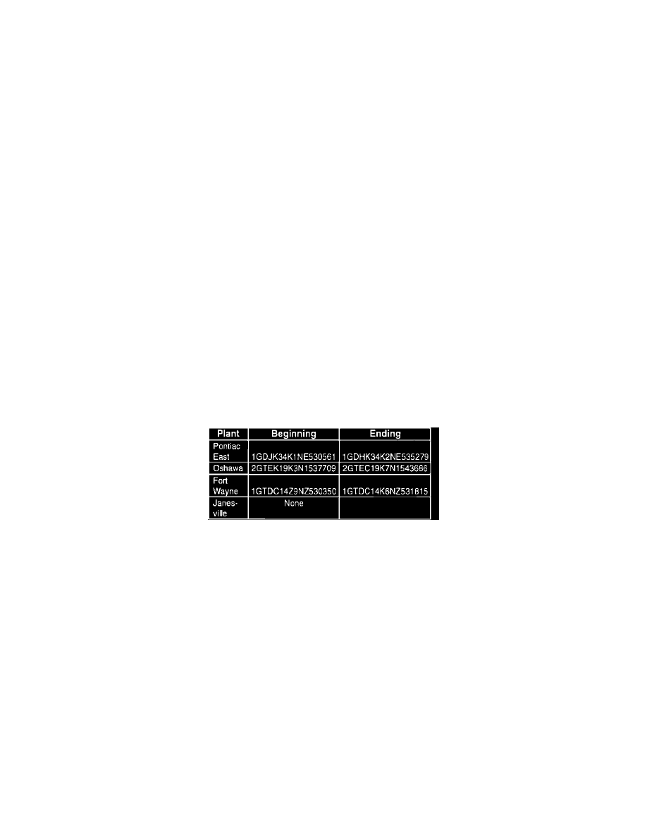
In addition to the 1988 GMC Truck C1 and C2 models, certain GMC Truck 1992 C1 and C2 models built within the VIN breakpoints are involved. (see
chart)
SERVICE PROCEDURE
1.
Inspect brake rotor for signs of contact with the lower control arm.
2.
If a gouge is found, replacement of the brake rotor will be necessary.
3.
Siphon 2/3 of the brake fluid from the master cylinder
4.
Remove the wheel and tire assembly.
5.
Remove the brake caliper from the brake rotor. Suspend the caliper assembly with a wire hook away from the work area.
6.
Remove wheel bearing cap and nut from the spindle.
7.
Remove the brake rotor and discard if a gouge is found. Care should be used so that the outer bearing and spindle threads are not damaged. Save
the bearings.
8.
Remove the brake splash shield and gasket.