
C 1500 Truck 2WD V6-262 4.3L VIN Z (1992)
3. Install Rotor and Bearing Puller Guide J 25031 to the front head and install Puller J 8433 with Poly-V-Belt Puller Leg Set J 24092 and remove the
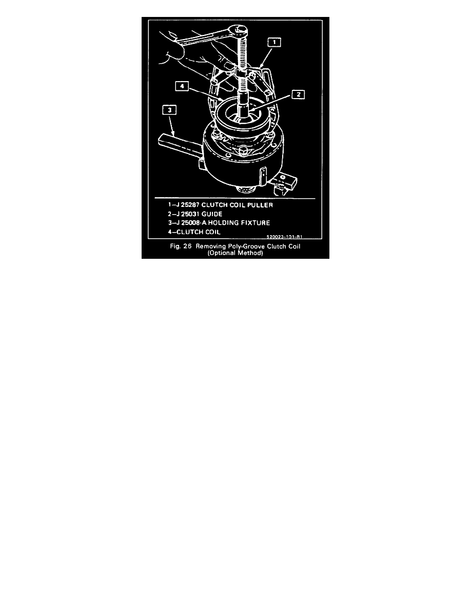
clutch coil from the front head (Fig. 25). Clutch coil may also be removed by using rotor and bearing puller guide J 25031 with puller tool J 25287
(Fig. 26).
Install or Connect
1. Place the clutch coil assembly on the neck of the front head with clutch coil terminals in line with mark described in Step 2 of the removal
procedure.
2. Place the pulley rotor and bearing assembly on the neck of the front head and seat the clutch coil and pulley rotor in place using Rotor and Bearing
Installer J 26271-A (Fig. 14).
Before fully seating the assembly on the front head, be sure the clutch coil terminals are in proper location in relation to the compressor and that
the three protrusions on the rear of the clutch coil housing align with the locator holes in the front head.
3. Install the pulley-rotor and bearing assembly retaining ring and reassemble the clutch plate and hub assembly.
4. Check to see that the clutch plate to clutch rotor air gap is 0.5-7.6mm (0.020-0.030").