
C 1500 Truck 2WD V8-5.3L VIN T (1999)
Removal Procedure
IMPORTANT: Remove any debris from the PCM connector surfaces before servicing the PCM. Inspect the PCM module connector gaskets when
diagnosing/replacing the PCM. Ensure that the gaskets are installed correctly. The gaskets prevent contaminate intrusion into the PCM.
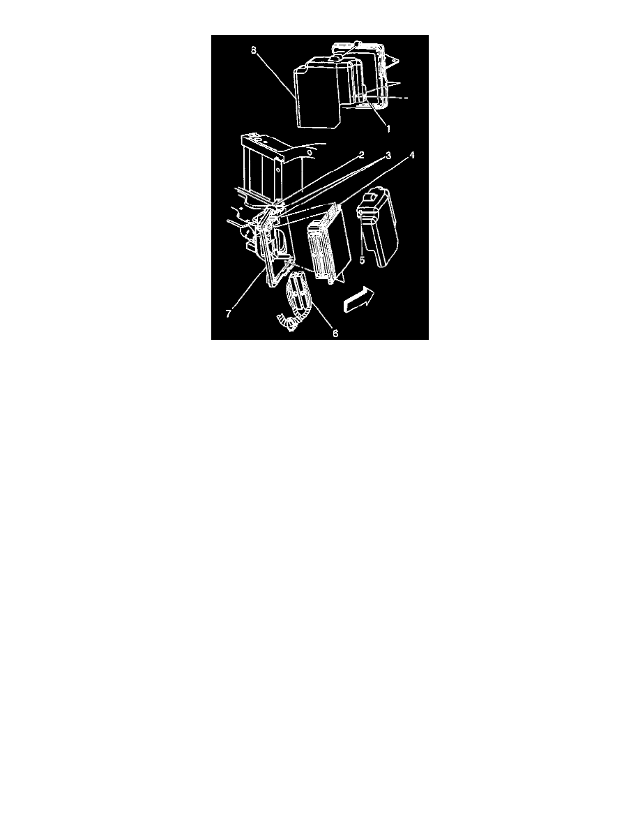
1. Release the PCM cover mounting holes (1, 5) away from the mounting tabs on the PCM mounting bracket.
2. Release the PCM cover (8) from the mounting bracket.
3. Remove the PCM cover.
NOTE: Do not touch the connector pins or soldered components on the circuit board in order to prevent possible electrostatic discharge (ESD)
damage to the PCM.
NOTE: In order to prevent internal damage to the PCM, the ignition must be OFF when disconnecting or reconnecting the PCM connector.
4. Disconnect the PCM harness connectors (6).
5. Release the spring latch (2) from the PCM.
6. Release the PCM mounting tabs (3) from the PCM.
7. Remove the PCM (4) from the engine compartment.
Installation Procedure
NOTE: Do not touch the connector pins or soldered components on the circuit board in order to prevent possible electrostatic discharge (ESD)
damage to the PCM.
NOTE: In order to prevent internal damage to the PCM, the ignition must be OFF when disconnecting or reconnecting the PCM connector.
1. Install the PCM (4) to the PCM mounting bracket (7) ensuring that the mounting tabs (3) are engaged.
2. Secure the spring latch (2) to the PCM.
3. Connect the PCM connectors (6) to the PCM (4).
Tighten
Tighten the PCM connector end fasteners to 8 N.m (70 lb in).
4. Install the PCM cover (8) to the PCM mounting bracket (7), ensuring the mounting tabs on the PCM mounting bracket are engaged into the
mounting holes in the PCM cover.
5. If a new PCM is being installed, program the EEPROM.
PCM Programming