
C 1500 Truck 2WD V8-5.3L VIN T (1999)
A Diagnostic System Check - Body Control System (Part 2 Of 2)
CIRCUIT DESCRIPTION
The Body Control Module (BCM) system check is a test in order to identify an electronic system malfunction. The BCM system check is the
starting point for any BCM concern. Understanding and using the BCM system check table will reduce diagnostic time. This prevents the
unnecessary replacement of parts.
TEST DESCRIPTION
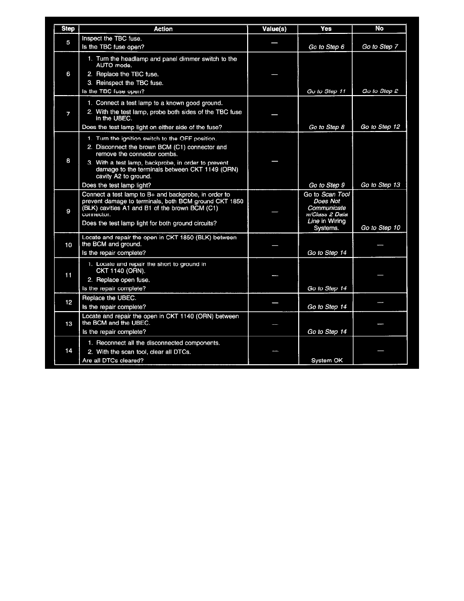
Step number(s) below refer to the same step number(s) in the BCM system check table.
1. This step determines if the Data Link Connector (DLC) can power up the scan tool.
2. Since most the diagnostic procedures require a scan tool, the serial data must be available. Step 1 is a test in order to ensure you can establish
communications with the BCM.
3. This step inspects for any Diagnostic Trouble Codes (DTCs) stored in the BCM. When the scan tool can read the DTCs, the serial data line is
functioning properly.
4. This step inspects for class 2 communications with other systems. When the scan tool can read data, the class 2 serial data line is functioning
properly.
5. This step inspects for the TBC fuses located in the Underhood Bussed Electrical Center (UBEC).
6. This step determines if CKT 352 (for the AUTO headlamps) is shorted to ground and blowing the TBC fuse.
7. This step determines if the UBEC is supplying voltage to the TBC fuse.
8. This step determines if the BCM power CKT 1140 is open between the BCM and the TBC fuse.
9. This step determines if the BCM ground CKT 1850 is open.
Diagnostic Information - Body Control Module (BCM) 1
DIAGNOSTIC INFORMATION