
C 1500 Truck 2WD V8-5.3L VIN T (1999)
9. Determine the difference between the MIN and MAX values.
-
If the variation between the recorded MIN and MAX voltage values is 1 volt or greater an intermittent open or high resistance condition exists.
Repair the condition as necessary.
-
If the variation between the recorded MIN and MAX voltage values is less than 1 volt an intermittent open or high resistance condition does
not exist.
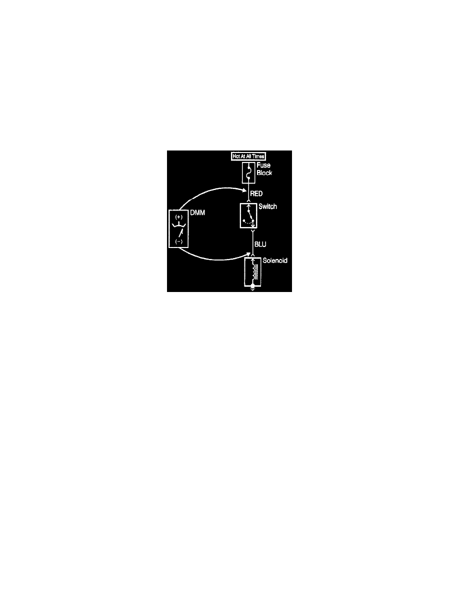
Measuring Voltage
The following procedure measures the voltage at a selected point in a circuit.
1. Apply power to the circuit.
2. Set the rotary dial of the DMM into the V (AC) or V (DC) position.
3. Connect the positive lead of the DMM to the point of the circuit to be tested.
4. Connect the negative lead of the DMM to a good ground.
5. Operate the circuit.
6. The DMM displays the voltage measured at that point.
Measuring Voltage Drop
Testing For Voltage Drop
The following procedure determines the difference in voltage potential between two points.
1. Set the rotary dial of the DMM to the V (DC) position.
2. Connect the positive lead of the DMM to one point of the circuit to be tested.
3. Connect the negative lead of the DMM to the other point of the circuit.
4. Operate the circuit.
5. The DMM displays the difference in voltage between the two points.
Testing For Continuity
The following procedures verify good continuity in a circuit.
With a DMM
1. Set the rotary dial of the DMM to the position.
2. Disconnect the power feed (i.e. fuse, control module) from the suspect circuit.
3. Disconnect the load.
4. Press the MIN MAX button on the DMM.
5. Connect one lead of the DMM to one end of the circuit to be tested.
6. Connect the other lead of the DMM to the other end of the circuit.
7. If the DMM displays low or no resistance and a tone is heard, the circuit has good continuity.
With a Test Lamp
IMPORTANT: Only use the test lamp procedure on low impedance power and ground circuits.
1. Remove the power feed (i.e. fuse, control module) from the suspect circuit.
2. Disconnect the load.
3. Connect one lead of the test lamp to one end of the circuit to be tested.
4. Connect the other lead of the test lamp to battery positive voltage.
5. Connect the other end of the circuit to ground.
6. If the test lamp illuminates (full intensity), then the circuit has good continuity.
Testing For Short to Ground