
C 1500 Truck 2WD V8-5.3L VIN T (1999)
Turn Signal Switch: Service and Repair
REMOVAL PROCEDURE
-
Tools Required
-
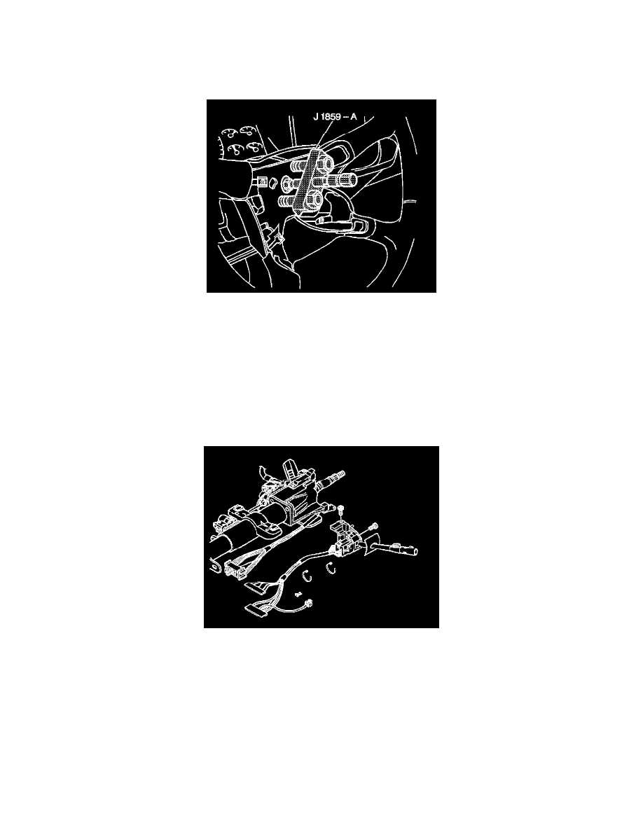
J 1859-A Steering Wheel Puller
1. Ensure the lever is in the center or the OFF position.
2. Disconnect the negative battery cable.
CAUTION: Refer to Battery Disconnect Caution in Service Precautions.
3. Disable the Supplemental Inflatable Restraint (SIR) system. Refer to Air Bag(s) Arming and Disarming.
4. Remove the inflator module. Refer to Infl Rst Steering Wheel Module Replacement in Air Bags and Seat Belts.
5. Remove the horn switch.
6. Remove the tilt lever. Refer to Tilt Lever Replacement - On Vehicle under Steering Column.
7. Remove the steering wheel nut.
8. Remove the steering wheel. Refer to Steering Wheel Replacement
9. Remove the knee bolster and the deflector. Refer to Knee Bolster Replacement in Instrument Panel, Gauges and Warning Indicators.
10. Loosen the steering column bracket nuts.
11. Remove the 2 TORX head screws from the lower column cover.
12. Tilt the cover down. Slide the cover back in order to disengage the locking tabs.
13. Remove the lower column cover.
14. Remove the TORX head screw from the upper column cover.
15. Remove the upper column cover.
16. Remove the 2 wire harness straps from the steering column wire harness.
17. Remove the Connector Position Assurance (CPA) retainer from the Brake Transmission Shift Interlock (BTSI).
18. Disconnect the steering column bulkhead connector from the vehicle wire harness.
19. Disconnect the gray and the black connectors of the switch from the column bulkhead connector.
20. Remove the 2 TORX head screws from the switch.
21. Remove the multifunction turn signal/hazard switch.