
C 1500 Truck 2WD V8-5.3L VIN T (1999)
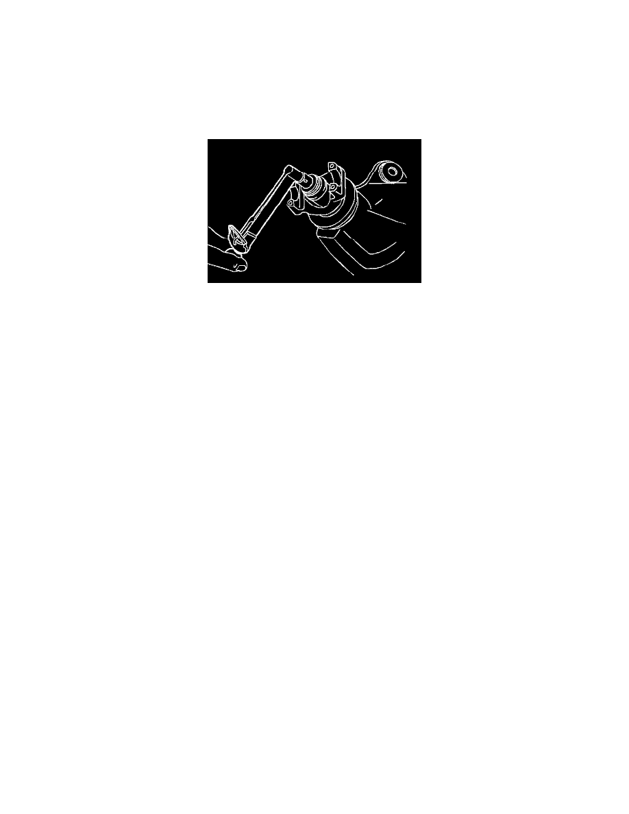
Important: Do not hammer the pinion flange onto the pinion stem.
3. Install the pinion flange (2) using the J 8614-01.
4. Use the alignment marks (1) in the installation of the pinion flange (2).
5. Install the washer and a new nut.
5.1.
Tighten the nut on the pinion stem as close as possible to the alignment marks without going past the marks.
5.2.
Use the alignment marks and the thread count as a reference.
5.3.
Tighten the nut a little at a time. Turn the pinion flange several times after each tightening in order to seat the rollers.
Important: If the recorded preload torque value was less than 4 Nm (3 ft. lbs.), reset the torque specification to 3 - 5 Nm (4 - 7 ft. lbs.).
6. Measure the torque required to rotate the pinion flange using the J 5853-B.
^
Compare the measured torque with the recorded value.
^
Continue tightening the pinion nut and measuring the torque until you achieve the recorded value.
7. Align the propeller shaft with the alignment marks.
8. Connect the propeller shaft. Refer to Refer to Propeller Shaft Replacement - One-Piece or Propeller Shaft Replacement - Two-Piece in Propeller
Shaft.
Notice: Refer to Fastener Notice in Service Precautions.
9. Install the retainers and the bolts.
^
Tighten the bolts to 20 Nm (15 ft. lbs.).
10. Fill the rear axle to the following levels.
^
8.6 inch ring gear rear axles 15 - 40 mm (0.6 - 1.6 inch) below the fill plug.
^
9.5 and 10.5 inch ring gear rear axles 10 mm (0.4 inch) below the fill plug.
11. Lower the vehicle.