
C 1500 Truck 2WD V8-6.5L DSL Turbo VIN F (1998)
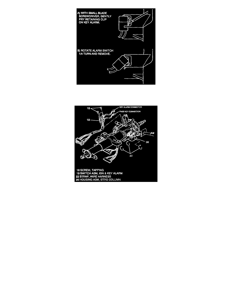
2. Alarm switch from lock module assembly (15).
^
Gently pry retaining clip on alarm switch with small blade screwdriver.
^
Rotate alarm switch 1/4 turn and remove.
3. Remove pass key connector (19) from lock module asm (15).
4. Two tapping screws (18).
5. Ignition & key alarm switch assembly (19).
^
Wire harness from slot in steering column housing assembly (26).
INSTALL OR CONNECT
NOTICE: Always use the correct fastener in the proper location. When you replace a fastener, use ONLY the exact part number for that application.
The manufacturer will call out those fasteners that require a replacement after removal. The manufacturer will also call out the fasteners that require
thread lockers or thread sealant. UNLESS OTHERWISE SPECIFIED, do not use supplemental coatings (paints, greases, or other corrosion inhibitors)
on threaded fasteners or fastener joint interfaces. Generally, such coatings adversely affect the fastener torque and joint clamping force, and may
damage the fastener. When you install fasteners, use the correct tightening sequence and specifications. Following these instructions can help you
avoid damage to parts and systems.
1. Ignition & key alarm switch assembly (19).
^
Route wire harness through slot in steering column housing assembly (26). Secure wire harness with a wire harness strap (22) through hole
located in the bottom of housing assembly (26).
2. Two tapping screws (18).
Tighten
^
Tighten screws (18) to 1.5 Nm (13 inch lbs.).
3. Alarm switch to lock module assembly (15).
A. Switch with retaining clip parallel to lock cylinder (I7).