
C 1500 Yukon 2WD V8-4.8L VIN V (2000)
Schematic
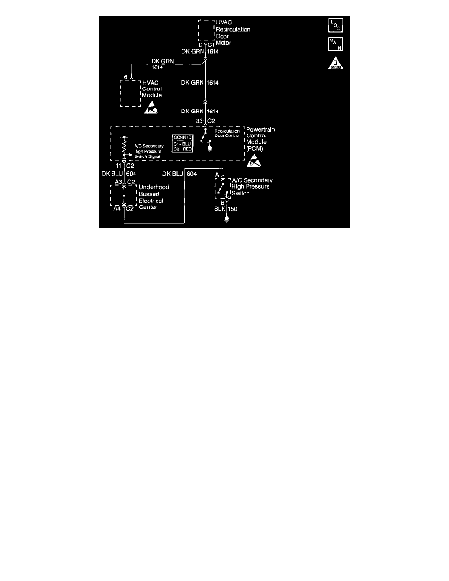
CIRCUIT DESCRIPTION
The A/C system uses a secondary A/C high pressure switch mounted on the high side of the A/C system near the condenser. The Powertrain Control
Module (PCM) utilizes this information in order to close the inlet air door recirculation door from the outside air when the A/C refrigerant pressure is
above a predetermined threshold. The working pressure of the A/C system is reduced by recirculating the cooler interior air instead of the hot
underhood ambient air.
The secondary A/C pressure switch is normally open. The PCM supplies a 12 volt signal to the secondary A/C high pressure switch. The other
terminal of the switch is connected to ground. The switch closes when the A/C pressure exceeds a predetermined threshold. The voltage signal from
the PCM goes low 0.0 volts when the secondary A/C high pressure switch closes. The PCM then commands the inlet air door closed to recirculate the
interior air.
The Heating, Ventilation, And Air Conditioning (HVAC) recirculation system consist of the following:
-
The A/C secondary high pressure switch
-
The PCM
-
The inlet air door and motor
-
The HVAC control module
The recirculation door is enabled any time the PCM detects the A/C high side pressure more than 350 psi. The minimum on-time for the recirculation
door is 40 seconds.
DIAGNOSTIC AIDS
IMPORTANT: Remove any debris from the PCM connector surfaces before servicing the PCM. Inspect the PCM connector gaskets when diagnosing
or replacing the PCM. Ensure that the gaskets are installed correctly. The gaskets prevent water intrusion into the PCM.
The recirculation button on the HVAC control head must be OFF when performing this diagnostic. Also, if the control circuit from either the HVAC
control head or the PCM control circuit is grounded, the air inlet door will remain in the recirculation mode regardless of PCM command or HVAC
control head command.
TEST DESCRIPTION
The numbers below refer to the step numbers on the diagnostic table.
4. This step is testing for a grounded signal wire, or for a secondary high pressure switch that is stuck closed.
6. This step tests if the HVAC control module can control the recirculation door. The glove box door can be lowered to view the operation of the
recirculation door.
9. This step allows the A/C system to build up a higher pressure, and verifies if the secondary A/C high pressure switch closes. The PCM should
command the recirculation door to the ON position as seen on the scan tool.
10. This step verifies if the PCM can control the recirculation door. The glove box door can be lowered to view the operation of the recirculation door.